
User's Manual
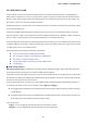
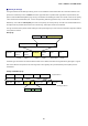
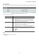
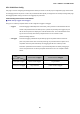
Table Of Contents
- 1. INTRODUCTION
- 2. INSTALLATION
- 3. SWITCH MANAGEMENT
- 4. WEB CONFIGURATION
- 4.1 Main Web Page
- 4.2 System
- 4.3 PoE Configuration
- 4.4 Basic Configuration
- 4.5 VLAN Configuration
- 4.6 QoS Configuration
- 4.7 ACL Configuration
- 4.8 Security
- 4.9 Advanced Features
- 4.10 Monitoring
- 5. COMMAND LINE INTERFACE
- 6. Command Line Mode
- 7. SWITCH OPERATION
- 8. Power over Ethernet Overview
- 9. TROUBLESHOOTING
- APPENDEX A: Networking Connection
- APPENDIX B: GLOSSARY

User’s Manual of FGSW-Series
85
4.5.3 VLAN Mode
The VLAN Mode Page provide VLAN Mode configuration supported by the Managed PoE+ Switch as the VLAN Mode screen in
Figure 4-5-2 appears.
Figure 4-5-2: VLAN Mode Configuration Page Screenshot
The Page includes the following fields:
Object Description
• VLAN Mode
Display the current VLAN mode used by this Managed PoE+ Switch.
Tag VLAN determines the VID of each entry and those ports are VLAN
members of which VLAN based on the settings of the Tag-based Entry.
Group VLAN determines which port in each group is its VLAN member
based on the settings of the Group-based Entry.
• Tag Method
This option only available in Tag VLAN mode.
By Tag- whether packet sent out add/remove tag is judged on the basis of
the value set by the port in the Tag-based entry.
By Port-whether the port sent out the packet add/remove tag is judged by
the tagging value set by the port in the VLAN port config web page
• Egress Frame
It could connect the selected packet type via engress rule to transport between
different VLAN groups. The available options are shown below:
Multicast
Unicast
ARP
Button
: press this button to take effect.