
User's Manual
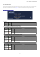
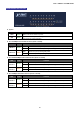
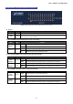
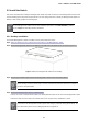
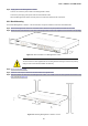
Table Of Contents
- 1. INTRODUCTION
- 2. INSTALLATION
- 3. SWITCH MANAGEMENT
- 4. WEB CONFIGURATION
- 4.1 Main Web Page
- 4.2 System
- 4.3 PoE Configuration
- 4.4 Basic Configuration
- 4.5 VLAN Configuration
- 4.6 QoS Configuration
- 4.7 ACL Configuration
- 4.8 Security
- 4.9 Advanced Features
- 4.10 Monitoring
- 5. COMMAND LINE INTERFACE
- 6. Command Line Mode
- 7. SWITCH OPERATION
- 8. Power over Ethernet Overview
- 9. TROUBLESHOOTING
- APPENDEX A: Networking Connection
- APPENDIX B: GLOSSARY

User’s Manual of FGSW-Series
30
Step5: Supply power to the Managed PoE+ Switch.
Connect one end of the power cable to the Managed PoE+ Switch.
Connect the power plug of the power cable to a standard wall outlet.
When the Managed PoE+ Switch receives power, the Power LED should remain solid Green.
2.2.2 Rack Mounting
To install the Managed PoE+ Switch in a 19-inch standard rack, please follow the instructions described below.
Step1: Place the Managed PoE+ Switch on a hard flat surface, with the front panel positioned towards the front side.
Step2: Attach the rack-mount bracket to each side of the Managed PoE+ Switch with supplied screws attached to the package.
Figure 2-5: Attach Brackets to the Managed PoE+ Switch.
You must use the screws supplied with the mounting brackets. Damage caused to the parts b
y
using incorrect screws would invalidate the warranty.
Step3: Secure the brackets tightly.
Step4: Follow the same steps to attach the second bracket to the opposite side.
Step5: After the brackets are attached to the Managed PoE+ Switch, use suitable screws to securely attach the brackets to the
rack, as shown in Figure 2-6.
Figure 2-6: Mounting Managed PoE+ Switch in a Rack