
User's Manual
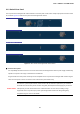
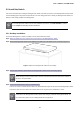
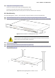
Table Of Contents
- 1. INTRODUCTION
- 2. INSTALLATION
- 3. SWITCH MANAGEMENT
- 4. WEB CONFIGURATION
- 4.1 Main Web Page
- 4.2 System
- 4.3 PoE Configuration
- 4.4 Basic Configuration
- 4.5 VLAN Configuration
- 4.6 QoS Configuration
- 4.7 ACL Configuration
- 4.8 Security
- 4.9 Advanced Features
- 4.10 Monitoring
- 5. COMMAND LINE INTERFACE
- 6. Command Line Mode
- 7. SWITCH OPERATION
- 8. Power over Ethernet Overview
- 9. TROUBLESHOOTING
- APPENDEX A: Networking Connection
- APPENDIX B: GLOSSARY

User’s Manual of FGSW-Series
29
2.2 Install the Switch
This section describes how to install your Managed PoE+ Switch and make connections to the Managed PoE+ Switch. Please
read the following topics and perform the procedures in the order being presented. To install your Managed PoE+ Switch on a
desktop or shelf, simply complete the following steps.
As the Managed PoE+ Switch have the same installation procedures, the FGSW-1816HPS
is picked to
be an example for describing hardware installation.
2.2.1 Desktop Installation
To install the Managed PoE+ Switch on desktop or shelf, please follow these steps:
Step1: Attach the rubber feet to the recessed areas on the bottom of the Managed PoE+ Switch.
Step2: Place the Managed PoE+ Switch on the desktop or the shelf near an AC power source, as shown in Figure 2-4.
Figure 2-4: Place the Managed PoE+ Switch on the Desktop
Step3: Keep enough ventilation space between the Managed PoE+ Switch and the surrounding objects.
When choosing a location, please keep in mind the environmental restrictions discussed in
Chapter 1,
Section 4, and specifications.
Step4: Connect the Managed PoE+ Switch to network devices.
Connect one end of a standard network cable to the 10/100/1000 RJ45 ports on the front of the Managed PoE+ Switch.
Connect the other end of the cable to the network devices such as printer server, workstation or router.
Connection to the Managed PoE+ Switch requires UTP Category 5 network cabling with RJ
45 tips. For
more information, please see the Cabling Specification in Appendix A.