
User's Manual
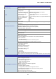
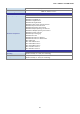
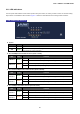
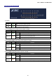
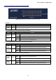
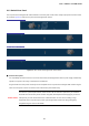
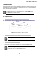
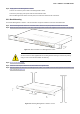
Table Of Contents
- 1. INTRODUCTION
- 2. INSTALLATION
- 3. SWITCH MANAGEMENT
- 4. WEB CONFIGURATION
- 4.1 Main Web Page
- 4.2 System
- 4.3 PoE Configuration
- 4.4 Basic Configuration
- 4.5 VLAN Configuration
- 4.6 QoS Configuration
- 4.7 ACL Configuration
- 4.8 Security
- 4.9 Advanced Features
- 4.10 Monitoring
- 5. COMMAND LINE INTERFACE
- 6. Command Line Mode
- 7. SWITCH OPERATION
- 8. Power over Ethernet Overview
- 9. TROUBLESHOOTING
- APPENDEX A: Networking Connection
- APPENDIX B: GLOSSARY

User’s Manual of FGSW-Series
28
2.1.3 Switch Rear Panel
The rear panel of the Managed PoE+ Switch indicates an AC inlet power socket, which accepts input power from 100 to 240V
AC, 50-60Hz. Figure 2-3 shows the rear panel of the Managed PoE+ Switch.
FGSD-1008HPS Rear Panel
FGSW-1816HPS Rear Panel
FGSW-2624HPS Rear Panel
FGSW-2624HPS 4 Rear Panel
Figure 2-3: Rear Panels of Managed PoE+ Switch Series
■ AC Power Receptacle
For compatibility with electric service in most areas of the world, the Managed PoE+ Switch’s power supply automatically
adjusts to line power in the range of 100-240V AC and 50/60 Hz.
Plug the female end of the power cord firmly into the receptalbe on the rear panel of the Managed PoE+ Switch. Plug the
other end of the power cord into an electric service outlet and the power will be ready.
Power Notice:
The device is a power-required device, which means it will not work till it is powered. If your networks
should be
active all the time, please consider using UPS (Uninterrupted Power Supply) for your device.
It will prevent you from network data loss or network downtime. In some areas, installing a surge
suppression device may also help to protect your Managed PoE+ Switch from being damaged by
unregulated surge or current to the Switch.