
User's Manual
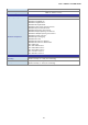
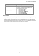
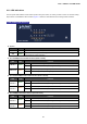
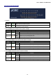
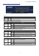
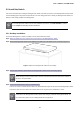
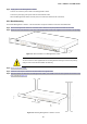
Table Of Contents
- 1. INTRODUCTION
- 2. INSTALLATION
- 3. SWITCH MANAGEMENT
- 4. WEB CONFIGURATION
- 4.1 Main Web Page
- 4.2 System
- 4.3 PoE Configuration
- 4.4 Basic Configuration
- 4.5 VLAN Configuration
- 4.6 QoS Configuration
- 4.7 ACL Configuration
- 4.8 Security
- 4.9 Advanced Features
- 4.10 Monitoring
- 5. COMMAND LINE INTERFACE
- 6. Command Line Mode
- 7. SWITCH OPERATION
- 8. Power over Ethernet Overview
- 9. TROUBLESHOOTING
- APPENDEX A: Networking Connection
- APPENDIX B: GLOSSARY

User’s Manual of FGSW-Series
23
2. INSTALLATION
This section describes the hardware features and installation of the Managed PoE+ Switch on the desktop or rack mount. For
easier management and control of the Managed PoE+ Switch, familiarize yourself with its display indicators, and ports. Front
panel illustrations in this chapter display the unit LED indicators. Before connecting any network device to the Managed PoE+
Switch, please read this chapter completely.
2.1 Hardware Description
2.1.1 Switch Front Panel
The front panel provides a simple interface monitoring the Managed PoE+ Switch. Figure 2-1 shows the front panels of the
Managed PoE+ Switches.
FGSD-1008HPS Front Panel
FGSW-1816HPS Front Panel
FGSW-2624HPS Front Panel
FGSW-2624HPS4 Front Panel
Figure 2-1: Front Panels of Managed PoE+ Switch Series Model
■ Fast Ethernet TP interface
10/100BASE-TX Copper, RJ45 Twisted-pair: Up to 100 meters.
■ Gigabit TP interface
10/100/1000BASE-T Copper, RJ45 Twisted-pair: Up to 100 meters.
■ SFP slots
1000BASE-X mini-GBIC slot, SFP (Small Factor Pluggable) transceiver module: From 550 meters to 2km (Multi-mode
fiber), up to above 10/20/30/40/50/60/70/120 kilometers (Single-mode fiber).
■ Reset button
At the left of the front panel, the reset button is designed for rebooting the Managed PoE+ Switch without turning off and on
the power. The following is the summary table of Reset button functions: