
User's Manual
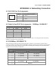
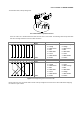
Table Of Contents
- 1. INTRODUCTION
- 2. INSTALLATION
- 3. SWITCH MANAGEMENT
- 4. WEB CONFIGURATION
- 4.1 Main Web Page
- 4.2 System
- 4.3 PoE Configuration
- 4.4 Basic Configuration
- 4.5 VLAN Configuration
- 4.6 QoS Configuration
- 4.7 ACL Configuration
- 4.8 Security
- 4.9 Advanced Features
- 4.10 Monitoring
- 5. COMMAND LINE INTERFACE
- 6. Command Line Mode
- 7. SWITCH OPERATION
- 8. Power over Ethernet Overview
- 9. TROUBLESHOOTING
- APPENDEX A: Networking Connection
- APPENDIX B: GLOSSARY

User’s Manual of WGSW-20160HP
APPENDEX A: Networking Connection
A.1 PoE RJ45 Port Pin Assignments
PIN NO
RJ45 POWER ASSIGNMENT
1
• Power +
2
• Power +
3
• Power -
6
• Power -
A.2 Switch's Data RJ45 Pin Assignments -- 1000Mbps, 1000BASE-T
Implicit implementation of the crossover function within a twisted-pair cable, or at a wiring panel, while not expressly
forbidden, is beyond the scope of this standard.
A.3 10/100Mbps, 10/100BASE-TX
When connecting your Switch to another Fast Ethernet switch, a bridge or a hub, a straight or crossover cable is
necessary. Each port of the Switch supports auto-MDI/MDI-X detection. That means you can directly connect the Switch
to any Ethernet devices without making a crossover cable. The following table and diagram show the standard RJ45
receptacle/ connector and their pin assignments:
RJ45 Connector pin assignment
PIN NO
MDI
Media Dependent Interface
MDI-X
Media Dependent Interface -- Cross
1
Tx + (transmit) Rx + (receive)
2
Tx - (transmit) Rx - (receive)
3
Rx + (receive) Tx + (transmit)
4, 5
Not used
6
Rx - (receive)
Tx - (transmit)
7, 8
Not used
PIN NO MDI MDI-X
1
BI_DA+
BI_DB+
2
BI_DA-
BI_DB-
3
BI_DB+
BI_DA+
4
BI_DC+
BI_DD+
5
BI_DC-
BI_DD-
6
BI_DB-
BI_DA-
7
BI_DD+
BI_DC+
8
BI_DD-
BI_DC-