
User's Manual


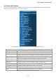
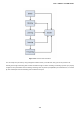
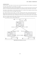
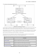
Table Of Contents
- 1. INTRODUCTION
- 2. INSTALLATION
- 3. SWITCH MANAGEMENT
- 4. WEB CONFIGURATION
- 4.1 Main Web Page
- 4.2 System
- 4.3 PoE Configuration
- 4.4 Basic Configuration
- 4.5 VLAN Configuration
- 4.6 QoS Configuration
- 4.7 ACL Configuration
- 4.8 Security
- 4.9 Advanced Features
- 4.10 Monitoring
- 5. COMMAND LINE INTERFACE
- 6. Command Line Mode
- 7. SWITCH OPERATION
- 8. Power over Ethernet Overview
- 9. TROUBLESHOOTING
- APPENDEX A: Networking Connection
- APPENDIX B: GLOSSARY

User’s Manual of FGSW-Series
139
3. Illustration of STP
A simple illustration of three switches connected in a loop is depicted in the below diagram. In this example, you can anticipate
some major network problems if the STP assistance is not applied.
If switch A broadcasts a packet to switch B, switch B will broadcast it to switch C, and switch C will broadcast it to back to switch
A and so on. The broadcast packet will be passed indefinitely in a loop, potentially causing a network failure. In this example,
STP breaks the loop by blocking the connection between switch B and C. The decision to block a particular connection is based
on the STP calculation of the most current Bridge and Port settings.
Now, if switch A broadcasts a packet to switch C, then switch C will drop the packet at port 2 and the broadcast will end there.
Setting-up STP using values other than the defaults, can be complex. Therefore, you are advised to keep the default factory
settings and STP will automatically assign root bridges/ports and block loop connections. Influencing STP to choose a particular
switch as the root bridge using the Priority setting, or influencing STP to choose a particular port to block using the Port Priority
and Port Cost settings is, however, relatively straight forward.
Figure 4-9-3: Before Applying the STA Rules