ET-118 Ethernet Fiber Optic Transceiver User’ s Manual
FCC Information The Federal Communication Commission Radio Frequency Interference Statement includes the following paragraph: This equipment has been tested and found to comply with the limits for a Class B Digital Device, pursuant to Part 15 of the FCC Rules. These limits are designed to provide reasonable protection against harmful interference in a residential installation.
exceeded. To prevent the situation happening, people who work with the antenna should be aware of the following rules: 1. Install the antenna in a location where a distance of 6.5 cm from the antenna may be maintained. 2. While installing the antenna in the location, please do not turn on the power of wireless card. 3. While the device is working, please do not contact the antenna. Copyright Copyright © 1999 Planet Technology Corp., all rights reserved.
CE Mark Warning This is a Class B product. In a domestic environment, this product may cause radio interference, in which case the user may be required to take adequate measures. About This Manual Ethernet Fiber Optic Transceiver Installation Guide is published by Planet Technology Corp. in 1999. This Revision is issued in Oct. 1999. Revision Ethernet Fiber Optic Transceiver ET-118 User’s Guide Part No.
Contents General Descriptions............................ Introduction....................................... Features............................................. AUI (D-15) connector descriptions... ST Connector.................................... LED Indicators.................................. Duplex Fiber Cable........................... Absolute Maximum Ratings............. Setting and Installation........................ Setting the SQE Switch.................... Installation.........................
Chapter 1 General Descriptions 1.1 Introduction The fiber Optic Medium Attachment Unit provides the complete Attachment Unit Interface (AUI) to fiber optic interface. It connects to any standard IEEE802.3 Data Terminal Equipment AUI connector, and requires no configuration. It is connected through a standard AUI cable or direct connection to an Ethernet board or Ethernet device unit via the AUI port.
− − Allow SQE (heartbeat) to be disabled when used with a concentrator / hub / repeater When SQE test switch is enabled, send a heartbeat signal to the attached station at the end of a transmission 1.
1.
1.5 LED Indicators LED MARK STATE DESCRIPTONS Power PWR Link Link Transmit Tx Collision Col On The transceiver has been connected Off Not connection On Link Beat Enable: A good link has been established with a functioning device Off Link Test signal is not received Blink Data packet is transmitted. Off No data packet is transmitted. On Large data is being transmitted Blink A collision is detected. Off No collision is detected. On Maybe there’s a problem with the transceiver. 1.
1.7 Absolute Maximum Ratings Ambient operating temperature Storage temperature Operating relative humidity Storage relative humidity Power Input voltage: Maximum input current: 0°C to +50°C -20°C to +85°C 8% to 80% RH 5% to 98% RH 10.2VDC to 15.
Chapter 2 Setting and Installation 2.1 Setting the SQE Switch When this transceiver is connected directly to a repeater, the SQE function must be disabled. Note that a 10Base-T concentrator is a repeater unit. SQE Test: § Default: enable § Enable: attaching the transceiver to a LAN card in a computer, or to device expecting the SQE test signal such as bridge or router § Disable: attaching the transceiver to a hub’s or repeater’s AUI port 6 2.
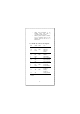
Figure 2-1 Connecting to Ethernet Board through AUI Port § Connecting to Ethernet Repeater through AUI port Figure 2-2 Connecting to Ethernet Repeater Through AUI Port Part No.