
Quick Guide

19
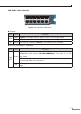
LEDs
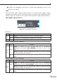
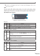
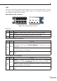
The front panel LEDs indicate instant status of port links and data activity. It helps
to monitor and troubleshoot when needed. Figure 4-10 shows the front panel of
the Standard Chassis Switch Module.
CS6-S24T24S LED indication
CS6-S24T24S
Console
9600, N, 8, 1
Alarm
SYS
26 28 30 32 34 36 38 40 42 44 46 48
25 27 29 31 33 35 37 39 41 43 45 47
2 4 6 8 10 12 14 16 18 20 22 24
1 3 5 7 9 11 13 15 17 19 21 23
CS6-S24T24S
Console
9600, N, 8, 1
Alarm
SYS
26 28 30 32 34 36 38 40 42 44 46 48
25 27 29 31 33 35 37 39 41 43 45 47
2 4 6 8 10 12 14 16 18 20 22 24
1 3 5 7 9 11 13 15 17 19 21 23
Figure 4-10 CS6-S24T24S LED Panel
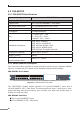
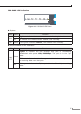
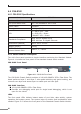
z System
LED Color Function
ALM
Green Lights to indicate that an alarm occurs in the single board
O To indicate the Chassis Switch Module runs normally.
SYS Green If the green indicator ickers, the module runs normally.
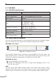
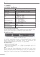
z 10/100/1000BASE-T Interfaces
LED Color Function
LNK/
ACT
Green
Lights to indicate the link through that port is successfully
established with speed 10/100/1000Mbps. The port is in the
“up” state.
Blinks to indicate that the Management Module is actively sending
or receiving data over that port.
O
Ifthe greenindicatoris o,the portis inthe“down” (notworking)
state.
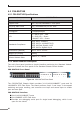
z 1000BASE-X SFP Interfaces
LED Color Function
LNK/
ACT
Green
Lights to indicate the link through that port is successfully
established with speed 1000Mbps. The port is in the “up” state.
Blinks to indicate that the Management Module is actively sending
or receiving data over that port.
O
Ifthe greenindicatoris o,the portis inthe“down” (notworking)
state