
Quick Guide

11
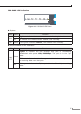
Provides one debugging serial port for single board debugging, which is not
open for the clients.
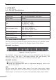
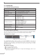
LEDs
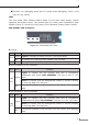
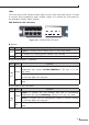
The front panel LEDs indicate instant status of port links, data activity, system
operation and system power. The system helps to monitor and troubleshoot when
needed. Figure 4-2 shows the front panel of the Standard Chassis Switch Module.
CS6-S24S8X LED Indication
Console
9600, N, 8, 1
Alarm
SYS
T4
T3
T2
T1
T8
T7
T6
T5
4
3
2
1
8
7
6
5
12
11
10
9
16
15
14
13
20
19
18
17
24
23
22
21
T6 T7 T8
10GBASE-X SFP+
CS6-S24S8X
1G 10G
Figure 4-2 CS6-S24S8X LED Panel
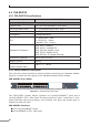
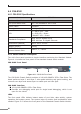
z System
LED Color Function
ALM
Green Lights to indicate an alarm occurs in the single board.
O To indicate the Chassis Switch Module runs normally.
SYS Green If the green indicator ickers, the module runs normally.
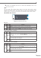
z 100/1000BASE-X SFP Interfaces
LED Color Function
LNK/
ACT
Green
Lights to indicate the link through that port is successfully
established with speed 100/1000Mbps. The port is the in “up”
state.
Blinks to indicate that the Management Module is actively sending
or receiving data over that port.
O
Ifthe greenindicatoris o,the portis inthe“down” (notworking)
state.
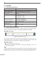
z 1G/10GBASE-X SFP+ Interfaces
LED Color Function
LNK/
ACT
Green
Lights to indicate the link through that port is successfully
established with speed 1G/10GMbps. The port is in the “up” state.
Blinks to indicate that the Management Module is actively sending
or receiving data over that port.
O
Ifthe greenindicatoris o,the portis inthe“down” (notworking)
state.