6-slot Layer 3 IPv6/IPv4 Routing Chassis Switch CS-6306R Quick Installation Guide
Table of Contents 1. Package Contents........................................................................................ 3 2. Physical Description..................................................................................... 4 3. Hardware Installation................................................................................... 6 3.1 Desktop Installation.............................................................................. 6 3.2 Rack-mounting Installation............................
1. Package Contents Thank you for purchasing PLANET 6-slot Layer 3 IPv6/IPv4 Routing Chassis Switch, CS-6306R. “Chassis Switch” mentioned in this quick installation guide refers to the CS-6306R. Open the box of the Chassis Switch and carefully unpack it.
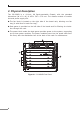
2. Physical Description The CS-6306R is a 19-inch, 9U Rack-mountable Chassis, with the standard dimensions (W x D x H) of 482 x 397 x 370 mm. The chassis consists of module slot and power supply slot. zz The fan block is located on the right side of the board rack, allowing one fan tray (4 axial fans for each fan tray). zz Dust gauze is provided on the left side of the board rack for filtering air circulation through the rack.
Figure 2-2 CS-6306R Rear Panel 1. Power slots Used for system power supply modules and supports up to three 550W AC/DC modules (CS6-PWR550-AC/DC). 2. Management slots Slots 5 and 6 support management module like CS6-MCU. (Slot 5 Master) 3. Switch slots Slots 1 to 4 support Switch modules like CS6-S16X and CS6-S24S8X 4. Fan tray slot Supports one system fan assembly with each assembly consisting of four axial fans. 5. Dust gauze slot Exterior air inlet for the ventilation subsystem.
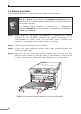
3. Hardware Installation During the installation and use of the CS-6306R Chassis Switch, please follow the steps below: 1. Chassis Switch Mounting Desktop installation Rack-mounting installation 2. Chassis Switch grounding 3. Modules installation 4. Removing and installing the dust gauze 5. Removing and installing the fan tray 6. Remover and installing the power supply 3.1 Desktop Installation To avoid damage, do not place any weight on the CS-6306R.
3.2 Rack-mounting Installation During the installation, please make sure the device does not slip from your grasp, or else it may cause damage to the device or may even hurt the installer. Please also note the hardware must be placed in the rack properly; if not, the hardware may fall off from the rack, causing harm to someone nearby. Double-check it after the installation. To install the CS-6306R in a 19-inch standard rack, follow the instructions described below.
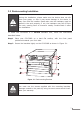
Step 3 After the brackets are attached to the CS-6306R, use suitable screws to securely attach the brackets to the rack, as shown in Figure 3-2. Please make sure the device does not slip through your grasp, or else it may cause damage to the device or may even hurt the installer. The handles are designed for sliding into cabinet only; please don’t use handles to lift the Chassis Switch. Console 9600, N, 8, 1 Console Figure 3-2 Mounting the CS-6306R in a Rack 3.
Lightning Protection Grounding The lightning protection system is an independent system consisting of a lightning rod, conductor and connection joint with the grounding system. The grounding system usually is shared with the power reference grounding, and green and yellow ground cable grounding. Lightning protection grounding is a building requirement, not a specific requirement of the Chassis Switch.
3.4 Module Installation The installation procedure is the same for all cards, as shown below: Slot 5 or Slot 6 should install with Management Module before powering on the Chassis Switch; otherwise, the Chassis Switch will not operate normally. The Chassis Switch supports a maximum of 2 Management modules (CS6-MCU) for the purpose of management redundancy at Slot 5 and Slot 6. Step 1 Power down the CS-6306R (Hot-swapping is supported by optional modules for the CS-6306R.
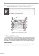
3.5 Removing and Installing the Dust Gauze Dust gauze is provided in the CS-6306R, which can be installed and removed from the back of the CS-6306R in right section. The dust gauze is meant to prevent large debris or particles in the air from being ingested into the Chassis Switch. Please perform cleaning on a regular basis according to the site conditions. Follow steps below: Step 1 Loosen the 2 panel fasteners in the dust gauze. Step 2 Draw the dust gauze out smoothly by holding the 2 screws.
3.6 Removing and Installing the Fan Tray One fan tray in the right section of the CS-6306R can be serviced from the front. The installation and removal of the fan tray is relatively simple. Please refer to the following procedure for reference. Removing the Fan Tray Step 1 Loosen the 2 screws on the front panel of the fan tray. Step 2 Hold the handle on the front panel of the fan tray with your middle and ring fingers, press the locker slightly down, and the fan tray can be drawn out smoothly.
3.7 Installing and Removing the Power Supply Unit Power down the CS-6306R (Hot-swapping is supported by power supply modules for the CS-6306R. However, for better convenience, it is recommended to power down the CS-6306R before installing the power supply modules) To install a power supply unit into the CS-6306R, please slide it into the compartment. To remove a power supply unit from the CS-6306R, press and hold the blue lever to the left till it is totally pulled out from the power supply unit.
3.8 Installing Wire Rack in the Chassis Switch You can see the front side of the CS-6306R with the wire rack slot in the left section .The installation and removal of the wire rack is relatively simple. Please refer to the following procedure for reference. Step 1 Combine three of the wire rack unit. Step 2 Install it in the wire rack and fasten 6 screws into the CS-6306R on the left section, as shown in Figure 3-7.
4. Chassis Switch Management To set up the Chassis Switch, the user needs to configure the Chassis Switch for network management. The Chassis Switch provides two management options: Out-of-Band management and In-Band management. Out-of-Band Management Out-of-band management is the management through Console interface. In-Band Management In-band management refers to the management by logging to the Chassis Switch using Telnet, HTTP, or using SNMP management software to configure the Chassis Switch.
5. Requirements Workstations running Windows XP/2003/Vista/7/8/2008/10, MAC OS X or later, Linux, UNIX, or other platforms are compatible with TCP/IP protocols. zz Serial Port Connection (Terminal) The above Workstations come with COM Port (DB9) or USB-to-RS232 converter. The above Workstations have been installed with terminal emulator, such as Tera Term or PuTTY. Serial cable -- one end is attached to the RS232 serial port, while the other end to the console port of the Managed Switch.
6. Terminal Setup To configure the system, connect a serial cable to a COM port on a PC or notebook computer and to serial (console) port of the CS-6306R Chassis Switch. The console port of the Chassis Switch is DCE already, so that you can connect the console port directly through PC without the need of Null Modem.
6.1 Logging on to the Console Once the terminal is connected to the Chassis Switch, power on the CS-6306R Chassis Switch, and the terminal will display “running testing procedures”. Then, the following message asks the login user name and password. The factory default user name and password are as follows and the login screen in Figure 6-3 appears. Username: admin Password: admin Figure 6-3 CS-6306R Chassis Switch Console Login Screen The user can now enter commands to manage the Chassis Switch.
6.2 Configuring IP Address Management Port The IP address configuration commands for Management module interfaces are listed below: Switch# enable Switch# config Switch_config# interface gigaEthernet 5/0 Switch_config_g5/0# ip address 192.168.1.1 255.255.255.0 The previous command would apply the follow settings for the Chassis Switch. IPv4 Address: 192.168.1.1 Subnet Mask: 255.255.255.
The previous command would apply the following settings for the CS-6306R. IPv4 Address: 192.168.0.100 Subnet Mask: 255.255.255.0 Figure 6-5 Configuring IPv4 Address of Interface VLAN 1 Screen To check the current IP address or modify a new IP address for the Chassis Switch, please use the procedure as follows: Show the current IP address 1. On “Switch#” prompt, enter “show ip interface brief”. 2. The screen displays the current IP address, Subnet Mask and Gateway as shown in Figure 6-6.
6.3 Telnet Management Log in to the Telnet configuration interface. The commands used in the Telnet CLI interface after login is the same as that in the Console interface. Default IP Address: 192.168.1.1 Username: admin Password: admin Figure 6-7 Telnet Configuration Interface 6.4 Saving the Configuration In Chassis Switch, the running configuration file stores in the RAM.
7. Starting Web Management The CS-6306R, like the CS6-S16X and CS6-S24S8X, needs a switch module to configure to Web Management by Interface VLAN 1. Chassis Switch PC / Workstation with IE Browser MGMT IP Address: 192.168.1.x RJ45/UTP Cable IP Address: 192.168.1.1 Figure 7-1 IP Management Diagram The following shows how to start up the Web Management of the Managed Switch. Note the Managed Switch is configured through an Ethernet connection.
7.1 Web Login the Chassis Switch 1. Use Internet Explorer 8.0 or above Web browser, enter IP address http://192.168.1.1 (that you have just set in console) to access the Web interface. 2. When the following dialog box appears, please enter the configured user name “admin” and password “admin” (or the username / password you have changed via console). The login screen in Figure 7-2 appears. Default IP Address: 192.168.1.
3. After entering the password, the main screen appears as shown in Figure 7-3. Figure 7-3 Web Main Screen of CS-6306R Chassis Switch 4. The Chassis Switch Menu on the left side of the Web page lets you access all the commands and statistics the Chassis Switch provides. Now, you can use the Web management interface to continue the Chassis Switch management or manage the Chassis Switch by console interface. Please refer to the user manual for more detailed information.
7.2 Saving Configuration via the Web To save all applied changes and set the current configuration as a startup configuration, the startup-configuration file will be loaded automatically across a system reboot. Click “Save All” on the top control bar. “Save All” function is equivalent to the execution of the write all command.
8. Recovering Back to Default Configuration Logging on to the console, the user can now enter commands to Recovering Back to Default Configuration. For a detailed description of the commands, please refer to the following sections.
9. Customer Support Thank you for purchasing PLANET products. You can browse our online FAQ resource at the PLANET Web site first to check if it could solve your issue. If you need more support information, please contact PLANET support team. PLANET online FAQs: http://www.planet.com.tw/en/support/faq.php?type=1 Support team mail address: support@planet.com.tw CS-6306R User’s Manual https://www.planet.com.tw/en/support/download.