Industrial Renewable Power 5-Port Gigabit Managed Switch/Router with 4-Port 802.
Safety Precautions Please read the following before using: 1. All electrical work must be done in accordance with local, and/or international electrical codes. 2. Before installing or using this device, read all instructions and cautionary marking located in (or on) this guide, the controller, the batteries, PV (Photovoltaic) array and any other device used. 3.
Table of Contents 1. Package Contents........................................................................................ 4 2. Requirements.............................................................................................. 5 3. Hardware Introduction................................................................................. 6 3.1 Front Panel.......................................................................................... 6 3.2 LED Indicators.....................................
1. Package Contents Thank you for purchasing PLANET Industrial Renewable Energy Managed PoE Switch/Router, BSP-360. Open the box of the BSP-360 and carefully unpack it. The box should contain the following items: 1 x BSP-360 1 x Wall Mounting Kit 1 x Quick Installation Guide 1 x DIN-rail Kit 5 x RJ45 Dust Cap If any of these are missing or damaged, please contact your dealer immediately.
2. Requirements PLANET BSP-360 provides a remote login interface for management purposes. The following equipment is necessary for further management: Workstation is installed with Ethernet NIC (Network Interface Card) Choice of Internet browsers includes Windows XP/2003, Vista, Windows 7, Windows 8, Windows 10, Windows 11, MAC OS X, Linux, Fedora, Ubuntu or other platforms compatible with TCP/IP protocols. The above workstation is installed with Web browser and JAVA runtime environment plug-in.
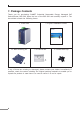
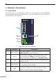
3. Hardware Introduction 3.1 Front Panel The front panel of the BSP-360 consists of 5 auto-sensing 10/100/1000Mbps Ethernet RJ45 ports and one USB interface. The LED Indicators are also located on the RJ45 ports of the BSP-360. PWR Alarm PV System 50W 100W 120W PoE Power Usage 1 3 4 LNK ACT PoE-in-Use 3 4 5/WAN Reset V1+ V2+ 5 DC Ouput: 24V , 2A max.
3.2 LED Indicators System LED Color PWR Green Alarm Red Function On To indicate BSP-360 has power. Slow Blinks To indicate PV < 24V.* Fast Blinks To indicate battery voltage is ≤ LVD.* Slow Blinks To indicate the system is “Not Charging”. Fast Blinks To indicate the battery is “Charging”. PV System Green 50W Amber On To indicate the system consumes over 50-watt PoE power budget. 100W Amber On To indicate the system consumes over 100-watt PoE power budget.
3.3 Upper Panel The upper panel of the BSP-360 consists of one terminal block connector with PV and battery power inputs. make sure the V+ & V is connected correctly, Warning Please and the wire gauge meets the maximum current. 1 2 3 4 5 6 V+ V+ PV Alarm Bat. Max. Fault Alarm Loading: 24V, 1A Battery DC Input: 24V , 10A , 8.8A max.
Battery In/Out 24V DC Please make sure the V+ & V is connected correctly, Warning and the wire gauge meets the maximum current. DC DC 24V DC 1 2 3 4 5 6 V+ V+ PV Alarm Bat. Max. Fault Alarm Loading: 24V, 1A Battery DC Input: 24V , 10A , 8.8A max. PV DC Input: 24-45V Battery Note The wire gauge for the terminal block should be in the range from 16 to 20 AWG. Fault Alarm Connectors The fault alarm contacts are in the middle (3 & 4) of the terminal block connector as the picture shows below.
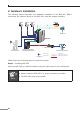
4. Hardware Installation The following section describes the hardware installation of the BSP-360. Before connecting any network device to the BSP-360, read this chapter carefully. CAM1 CAM2 CAM3 Battery DC DC PoE PoE PoE Solar PV PoE BSP-360 DC N 1000 Ethernet Switch Outdoor Wireless AP Media Converter/ DC Powered Device Monitoring Center N DC 2.4GHz 802.
Step 2. Installing battery DC DC 1 2 3 4 5 6 Max. Alarm Loading: 24V, 1A Battery DC Input: 24V , 10A PV DC Input: 24-45V , 8.8A max. Bat.In/Out Battery 1. Connect the negative electrode of the battery to the terminal for the negative electrode of the battery on the BSP-360. By default, the lithium battery is in use. 2. Connect the positive electrode of the battery to the terminal for the positive electrode of the battery on the BSP-360. 3.
Note Please link to PLANET Download Center and download BSP360PV&BAT_calculation. The calculation list can help you to select solar panel and battery. Refer to Section 6 for customer support. Step 3. Installing PV Panel DC DC 1 2 3 4 5 6 Max. Alarm Loading: 24V, 1A Battery DC Input: 24V , 10A PV DC Input: 24-45V , 8.8A max. Solar PV PV In 1. Connect the negative electrode of the PV panel to the terminal for the negative electrode of the PV panel on the BSP-360. 2.
Step 4. Connecting 802.3af/802.3at PoE Device PoE PoE PoE PoE 802.3af/at PoE Device 1. Connect the PoE devices to ports 1~4 on the BSP-360. 2. Check the PoE-in-Use LED. If the network devices such as PoE camera and PoE wireless AP are powered, the PoE-in-use LED will turn ON and Link/Act LED will blink for a successful connection or data receiving. Please use Cat5/5e or above cable and the maximum distance should within 100 meters.
Step 5. Wiring the DC Outputs Please follow the steps below to insert the power wires for DC power required equipment. 1. Please find the terminal block connector with two DC power outputs shown below: V1+ V2+ V1V22. Insert the Positive and Negative DC wires into the V+ and V- terminals, respectively; Terminals 1 and 3 for Power 1, and Terminals 2 and 4 for Power 2. 3. Connect the other points of DC power wires to the power devices. Tighten the wire-clamp screws for preventing the wires from loosening.
4. Install the terminal block on the BSP-360. a. The voltage of DC out is based on the battery voltage and the maximum DC out from the BSP-360 is 24VDC, 2A. Note b. The wire gauge for the terminal block should be in the range from 16 to 20 AWG. c. The external device should also be grounded properly. Please ensure the output voltage is correct for remote device. Otherwise, it will damage your remote device. Step 6. Connecting to PC or your remote Ethernet network.
5. Web Management The following shows how to start up the Web Management of the BSP-360. Note the BSP-360 is configured through an Ethernet connection. Please make sure the manager PC must be set to the same IP subnet address. For example, the default IP address of the BSP-360 is 192.168.0.100, then the manager PC should be set to 192.168.0.x (where x is a number between 1 and 254, except 100), and the default subnet mask is 255.255.255.0. RJ45/UTP Cable IP Address: 192.168.0.x BSP-360 IP Address: 192.
Step 3. After entering the password, the main screen appears. The above banner shows the information of Green Power, Total Power Usage, PoE Usage and Battery Capacity. Top Banner Step 4. The Function Menu on the left of the Web page lets you access all the functions and status the BSP-360 provides. Main Feature Banner Function Menu Now, you can use the Web management interface to continue the BSP-360 management. Please refer to the user manual for more details.
6. [OPTIONAL] Deployed Devices Monitored via NMS-360 Controller Note If you also have an NMS-360 controller, please refer to the following steps to set up the central management. The NMS-360 is used to centrally manage a large number of BSP-360. Therefore, you need to upgrade the BSP-360 firmware before using NMS-360. Please download and use the latest BSP-360 firmware from the website so that setting can be completed smoothly.
Step 2. BSP-360: Log in to the BSP-360 Web User Interface and enable both the SNMP and NMS controller functions. Enable “SNMP” Enable “NMS” Note If you want to use central management, and ONVIF monitoring functions, please refer to the user manual or NMS-360 series related profile.
7. Customer Support Thank you for purchasing PLANET products. You can browse our online FAQ resource on PLANET web site first to check if it could solve your issue. If you need more support information, please contact PLANET switch support team. Support team mail address: support@planet.com.tw BSP-360 User’s Manual: https://www.planet.com.tw/en/support/downloads?&method=keyword&keyword=B SP-360&view=3#list BSP-360 PV&BAT Calculation: https://www.planet.com.
Appendix A: Recommended Use of the Connected Wires The wire gauges for the current are shown below: Gauge Diameter Amp AWG #16 1.295 10.00 AWG #17 1.143 8.40 AWG #18 1.016 6.40 AWG #19 0.914 5.20 AWG #20 0.813 4.
Appendix B: Recommended Settings for Batteries Use Lead-acid battery for BSP-360. You could set the Battery type at Battery Management on the web of BSP-360. Use Lithium battery for BSP-360. You could set the Battery type at Battery Management on the web of BSP-360.
Appendix C: BSP-360 Battery Default Setting Battery Information Type Lithium Battery (Default) Lead-acid Battery FCV (Float Charge Voltage) 26.6V 27.2V ACV (Absorption Charge Voltage) 28.7V 29.2V LVD (Low Voltage Disconnection) 21.3V 22.2V LVR (Low Voltage Reconnection) 24.0V 23.5V Setting Default Charge Board LVD 21.3V Default Charge Board LVR 24.0V Copyright © PLANET Technology Corp. 2022. Contents are subject to revision without prior notice.