ADSL 2/2+ Router with USB Port ADE-3410 User's Manual 1
Copyright Copyright© 2008 by PLANET Technology Corp. All rights reserved. No part of this publication may be reproduced, transmitted, transcribed, stored in a retrieval system, or translated into any language or computer language, in any form or by any means, electronic, mechanical, magnetic, optical, chemical, manual or otherwise, without the prior written permission of PLANET.
This device complies with Part 15 of the FCC Rules. Operation is subject to the Following two conditions: (1) This device may not cause harmful interference, and (2) this Device must accept any interference received, including interference that may cause undesired operation. Federal Communication Commission (FCC) Radiation Exposure Statement This equipment complies with FCC radiation exposure set forth for an uncontrolled environment.
Table of Contents 1. Introduction ......................................................................................................................6 1.1 Feature ....................................................................................................................6 1.2 Package Contents....................................................................................................7 1.3 Physical Details......................................................................................
3.5.3.2 DMZ .....................................................................................................38 3.5.4 Routing .........................................................................................................38 3.5.4.1 RIP .......................................................................................................38 3.5.4.2 Static Route .........................................................................................39 3.5.5 IP QoS ..............................
1. Introduction The PLANET ADSL 2/2+ Router, ADE-3410, provides office and residential users the ideal solution for sharing a high-speed ADSL 2/2+ broadband Internet connection on one Ethernet port and one USB port. It can support downstream transmission rates of up to 24Mbps and upstream transmission rates of up to 3.5Mbps.
Dynamic DNS Support DDNS, when used with the Virtual Servers feature, allows users to connect to Servers on your LAN using a Domain Name, even if you have a dynamic IP address which changes every time you connect. VPN Pass through Support PCs with VPN (Virtual Private Networking) software using PPTP, L2TP, and IPSec are transparently supported - no configuration is required. RIP Routing It supports RIPv1/2 routing protocol for routing capability.
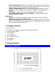
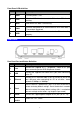
Front Panel LED definition LED Meaning 1 PWR Lit when power is ON. 2 Link Lit when DSL line is connected. Blink when DSL line is training. 3 Data Blink when DSL data is transferring. 4 LAN Lit when connected to an Ethernet device. Blink when data is Transmitted / Received. 5 USB Lit when the USB port is connected to the PC and working properly.
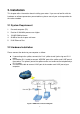
2. Installation This chapter offers information about installing your router. If you are not familiar with the hardware or software parameters presented here, please consult your service provider for the values needed. 2.1 System Requirement 1. Personal computer (PC) 2. Pentium III 266 MHz processor or higher 3. 128 MB RAM minimum 4. 20 MB of free disk space minimum 5. RJ45 Ethernet Port 2.
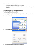
If do not need to connect to the splitter, z Connect the modem to wall jack with a RJ-11 cable. z Use Ethernet cable to connect “LAN” port of the modem and network adaptor of your computer. 2.3 Configuring the Network Properties Configuring PC in Windows XP 1. Go to Start / Control Panel (in Classic View). In the Control Panel, double-click on Network Connections 2. Double-click Local Area Connection. 3. In the Local Area Connection Status window, click Properties. 4.
5. Select the Obtain an IP address automatically and the Obtain DNS server address automatically radio buttons. 6. Click OK to finish the configuration. Configuring PC in Windows 2000 1. 2. Go to Start / Settings / Control Panel. In the Control Panel, double-click on Network and Dial-up Connections. Double-click Local Area Connection.
3. In the Local Area Connection Status window click Properties. 4. Select Internet Protocol (TCP/IP) and click Properties. 5. Select the Obtain an IP address automatically and the Obtain DNS server address automatically radio buttons. Click OK to finish the configuration. 6.
Configuring PC in Windows 98/Me 1. Go to Start / Settings / Control Panel. In the Control Panel, double-click on Network and choose the Configuration tab. 2. Select TCP/IP Æ NE2000 Compatible, or the name of your Network Interface Card (NIC) in your PC. 3. Select the Obtain an IP address automatically radio button. 4. Then select the DNS Configuration tab. 5. Select the Disable DNS radio button and click OK to finish the configuration.
3. Web Configuration Management Determine your connection settings Before you configure the router, you need to know the connection information supplied by your ADSL service provider. Connecting the ADSL Router to your network Unlike a simple hub or switch, the setup of the ADSL Router consists of more than simply plugging everything together.
Once you have powered on ADE-3410, system will boot up and connect to DSLAM automatically. In login dialog, enter “admin” as user name and “admin” as default password. After log in, you will see the following page. The default screen is Wizard setting screen. You can configure the device step by step. 3.1 ADSL Router Status The Status screen display system information of your Router. It includes the System, LAN, WAN, Port Mapping, Statistic and ARP Table.
3.1.2 LAN Status You can see the LAN IP address, Mask, DHCP status, MAC and DHCP Client Table in this screen. 3.1.3 WAN Status You can see the VPI/VCI, Encapsulation type, Protocol, WAN IP address, Gateway and DNS information in this screen.
3.1.4 Port Mapping You can see the Port Mapping information in this screen. It includes the status and Mapping Relation. 3.1.5 Statistic You can see the Statistic information in this screen. It includes the Traffic and DSL statistic. Traffic Statistic Screen The screen shows the statistic of LAN, WLAN and WAN Port. Click the Refresh button to refresh the information.
DSL Statistic The screen shows the ADSL line statistic. 3.1.6 ARP Table You can see the ARP information in this screen. Click the Refresh button to refresh the information.
3.2 Wizard You can use "Wizard" to setup the router as follows, and the router will connect to the Internet via ADSL line. Step 1. Click "Wizard" to get into the quick setup procedures. It will show the below screen. Enter the VPI / VCI value that provided by your ISP. Step 2. Click "Next" to select your WAN Connection Type. You can have this information from your Internet Service Provider.
Step 3. Click "Next" to setup to select the WAN IP type, and the WAN IP setting is provided by your ISP. Step 4. Enter the user name and password that your ISP has provided to you. Select the connection type that you want to use. There are three types for your selection – Continuous, Connect on Demand and Manual.
Step 5. Click "Next" to setup your LAN IP and DHCP Server setting. Step 6. Enter the Finish to save settings and reboot the device or click Back to modify your settings.
3.3 LAN The LAN setup includes two parts – LAN Interface and DHCP Settings. 3.3.1 LAN Interface Settings There are the IP settings of the LAN Interface for the device. These settings may be referred to as Private settings. You may change the LAN IP address if needed. The LAN IP address is provided to your internal network and cannot be seen on the Internet. You can change the LAN IP address for your requirements. The default LAN IP is 192.168.1.1.
3.3.2 DHCP Server Settings Enable the DHCP Server if you are using this device as a DHCP server. This page lists the IP address pools available to hosts on your LAN. The device distributes numbers in the pool to hosts on your network as they request Internet access. You can setup DHCP server to assign IP address to your PC automatically. You can also manually assign an IP according to the MAC address of PC’s network card.
IP Pool Range: Enter the start IP and end IP address you wish to use as the DHCP server's IP assignment. Show Client: It shows the current client which is connecting with your ADSL router. Max Lease Time: Enter the amount of time you wish to lease out a given IP address. Domain Name: Enter your domain name. Gateway Address: Enter the default gateway IP address. Default is the LAN IP address.
3.4 WAN 3.4.1 WAN Interface ADSL 2/2+ Router provide 8 PVCs with different channel mode. You can select the Bridge / MER / PPPoE / PPPoA mode for your environment. Bridge Mode The device can be configured to act as a bridging device between your LAN and your ISP. Bridges are devices that enable 2 or more networks to communicate as if they are 2 segments of the same physical LAN. ADSL 2/2+ Router is Bridge Mode enabled by factory default. 1. Open the WEB page in “WAN Æ WAN Interface”. 2.
function saves your changes from RAM to flash memory and then reboot the system. PPPoE / PPPoA Mode Select this option if your ISP requires you to use a PPPoE / PPPoA connection. This option is typically used for DSL service. Please enter the proper information in the fields. 1. Open the WEB page at “WAN Æ WAN Interface”. 2. Select the Channel Mode to “PPPoE”. Set the value of VPI / VCI and select the Encapsulation mode from your ISP. 3. Enter the User Name / Password from your ISP. 4.
MER Mode Select this option to set static IP information. You will need to enter in the encapsulation type, IP address, subnet mask, and gateway address provided to you by your ISP. Each IP address entered in the fields must be in the appropriate IP form, which is 4 IP octets separated by a dot (x.x.x.x). The Router will not accept the IP address if it is not in this format. 1. Open the WEB page at “WAN Æ WAN Interface”. 2. Select the Channel Mode to “1483 MER”.
3.4.2 ATM Settings The page is for ATM PVCs’ QoS mode setting. The device supports 4 QoS mode — UBR / CBR /rt-VBR / nrt-VBR. You can click the “ATM Setting” on the WAN Interface setting screen. ATM QoS: Select the Quality of Service types for this Virtual Circuit. The ATM QoS types include CBR(Constant Bit Rate), VBR(Variable Bit Rate) and UBR (Unspecified Bit Rate). These QoS types are all controlled by the parameters specified below, including PCR, SCR, and MBS.
MBS: Maximum Burst Size (MBS) is the maximum number of cells that can be sent at the PCR. After MBS is reached, cell rates fall below SCR until cell rate averages to the SCR again. At this time, more cells (up to the MBS) can be sent at the PCR again. “Apply Changes”: Set new PVC QoS mode and values for the selected PVC. “Undo”: Discard your settings. 3.4.3 ADSL Settings You can set ADSL connect mode here. It supports G.Lite, G.Dmt, T1.413, ADSL2 and ADSL2+.
3.5 Advance You can configure different advanced services in this part. It includes DNS, Firewall, Virtual Server, Routing, IP QoS, Anti-DoS, Port Mapping and Other. 3.5.1 DNS In this screen, you can modify the DNS server settings. It includes the DNS and DDNS functions.
Enable: Enable or disable DDNS. DDNS Provider: Choose the option of provider. It supports the DynDns and TZO. Hostname: Type the domain name assigned to your ADSL by your Dynamic DNS provider. DynDns Settings: Username: Type your user name. Password: Type the password assigned to you. TZO Settings: E-mail Address: Type your e-mail address. Key: Type your key number. Click the “Add” to add this DDNS entry or click “Remove” to delete the DDNS entry.
3.5.2 Firewall Firewall is an advance feature used to deny or allow traffic from passing through the device. ADSL router support some firewall related functions. It includes the IP/Port Filter, MAC Filter and URL Blocking. 3.5.2.1 IP/Port filtering Use the IP/Port filters to deny / allow particular LAN IP addresses from accessing the Internet. You can deny / allow specific port numbers or all ports for a specific IP address.
Rule Action: Select the Deny or Allow for your rules. Direction: Select the Outgoing or Incoming. Protocol: Set protocol type to be blocked or allowed. Src IP Address / Mask / Port: Set the subnet of source side computers to be denied / allowed access to the destination side computers. An individual source IP address can be designated for filtering. If all IP addresses must be filtered, leave this box blank. Enter the IP/subnet mask address in the form of XXX.XXX.XXX.XXX. Example: The IP address is 192.168.
3.5.2.2 MAC Filtering Use the MAC filters to deny computers within the local area network from accessing the Internet. Entries in Filter Table are used to restrict certain types of data packets from your local network to Internet through the Gateway. Use of such filters can be helpful in securing or restricting your local network. Default Action: Specify default filtering rule action to be either Deny or Allow if no other rules can be applied. Click the “Apply Changes” to apply your setting.
Src MAC Address: Set the MAC address of source side computers to be denied/allowed access to the destination side computers. Dst MAC Address: Set the MAC address of destination side computers to be denied/allowed access to the source side computers. Click “Add” button to add this filtering rule.
3.5.2.3 URL Block This page is used to configure the Blocked FQDN (Such as tw.yahoo.com) and filtered keyword. Here you can add / delete FQDN and filtered keyword. URL Blocking: Enable or Disable URL Blocking. Click the “Apply Changes” to apply your setting. URL Blocking: Enter the FQDN in the field and click the “Add FQDN” button to add this rule. Keyword Filtering: Enter the keyword which you want to block. Click “Add keyword” button to add this filtering rule.
3.5.3 Virtual Server The Virtual Server is the server or server(s) behind NAT (on the LAN), for example, Web server or FTP server, that you can make visible to the outside world even though NAT makes your whole inside network appear as a single machine to the outside world. The Virtual Server includes two parts – Services and DMZ. 3.5.3.1 Services Click “Add” to show the Virtual Server setting screen. Protocol: Choose proper protocols for your services.
3.5.3.2 DMZ A DMZ (Demilitarized Zone) allows a single computer on your LAN to expose ALL of its ports to the Internet. Enter the IP address of that computer as a DMZ (Demilitarized Zone) host with unrestricted Internet access. When doing this, the DMZ host is no longer behind the firewall. Enable DMZ: Click it to enable the DMZ function. Enter “DMZ Host IP Address” and click “Apply Changes” to activate the DMZ host. "Note Please Commit/Reboot if you want to make this settings effective immediately 3.5.
To activate RIP for the device, select the “Enabled” radio button for RIP Mode and click “Apply Changes” to apply it. To configure an individual interface, select the Interface, Receive Mode and Send mode. Click the “Add” button to save the configuration, and to start or stop RIP based on the Global RIP mode selected. 3.5.4.2 Static Route This page is used to configure the routing information. Here you can add / delete IP routes.
static route information. Destination: The IP address where packets will go to. Subnet Mask: The subnet mask of the destination IP address. Next Hop: The gateway that the packets will pass by during transmission. Metric: Metric represents the “cost” of transmission for routing purposes. IP Routing uses hop count as the measurement of cost, with a minimum of 1 for directly connected networks. Enter a number that approximates the cost for this link.
3.5.6 Anti-DoS "Denial-of-Service Attack" (DoS Attack), a type of attack on a network that is designed to bring the network to its knees by flooding it with useless traffic. This page is used to prevent DOS attacks that you configure. Select “Enable” can automatically detect and block Denial of Service (DoS) attacks, such as Ping of Death, SYN Flood, Port Scan and Land Attack. Select the attack types that you want to block and click “Apply Changes” to apply your settings.
3.5.7 Port Mapping Port Mapping supports multiple ports to PVC and bridging groups. Each group will perform as an independent network. To support this feature, you must create mapping groups with appropriate LAN and WAN interfaces using the “->” button. The “<- “button will remove the grouping and add the ungrouped interfaces to the Default group. To manipulate a mapping group: "Note 1. Select a group from the table. 2.
3.5.8 Other This function includes as following parts – IGMP Proxy, UPnP and Bridge. 3.5.8.1 IGMP Proxy IGMP Proxy enables the system to issue IGMP host messages on behalf of hosts that the system discovered through standard IGMP interfaces. The system acts as a proxy for its hosts when you enable it by doing the follows: Enable IGMP proxy on WAN interface (upstream), which connects to a router running IGMP. Enable IGMP on LAN interface (downstream), which connects to its hosts.
Click “Enable” to enable UPnP function and select the WAN Interface. Click “Apply Changes” to apply your setting. "Note Please Commit/Reboot if you want to make this settings effective immediately 3.5.8.3 Bridge This page is used to configure the bridge parameters. Here you can change the settings or view some information on the bridge and its attached ports. Aging Time: Enter the time for the bridge. 802.1d Spanning Tree: You can Enable or Disable the 802.1d Spanning Tree Protocol.
3.6 Admin You can configure admin management in this part. It includes Remote Access, Commit / Reboot, Password, Backup / Restore, Update Firmware, Time Zone, System Log, SNMP, TR-069, and ACL. 3.6.1 Remote Access User can enable or disable remote management services for the LAN and WAN. Select the service items which you want to remote management. Click “Apply Changes” to apply your setting. 3.6.
3.6.3 Password This page is used to set the account to access the web server of ADSL Router. The new password will be availability after system reboot. User Name: There are two level user accounts for your selection. The admin account has full rights for device management, and the user account only can see the status information of this device. Old Password: Enter the old password. New Password: Enter your new password. Confirmed Password: Enter your new password again.
3.6.4 Backup / Restore This page allows you to backup current settings to a file or restores the settings from the file which was saved previously. Backup: Click the “Save…” button to backup the configuration of router. Restore: Click the “Browse...” button, select the correct update configure settings file. Then click the “Upload” to update the configurations. 3.6.5 Upgrade Firmware You can upgrade the firmware of the router in this page.
3.6.6 Time Zone The system time is the time used by the device for scheduling services. You can manually set the time or connect to a NTP (Network Time Protocol) server. If an NTP server is set, you will only need to set the time zone. Current Time: It shows the current time. Time Zone: Choose the Time Zone of your location. This will set the time difference between your time zone and Greenwich Mean Time (GMT).
3.6.7 System Log Click “System Log” to show the log information of device. The system log dialog allows you to view the system log and click the “Refresh” button to fresh the system event logs. System Log: You can Enable or Disable the System Log Function. Click “Apply Changes” to apply your setting.
3.6.8 SNMP This page is used to configure the SNMP protocol. You can set SNMP related information here. Read Community: Select to set the password for incoming Get- and GetNext request from management station. Write Community: Select to set the password for incoming Set request from management station. The default password is “public”. When you are done making changes, click “Apply Changes” to apply your setting.
3.6.9 TR-069 This page is used to configure the TR-069 CPE. Here you may change the setting for the ACS's parameters. 3.6.10 ACL Access Control List Configuration If enabled, permits access to local management services from IP addresses contained in the Access Control List.
If enable ACL, and then only the effective IP in ACL can access the router. Step1 If you want to enable ACL, please choose "Enable" and then press "Apply Changes" to apply your setting. Step2 Click the Enable checkbox. Step3 Enter the host IP address that you want to permit and click “Add”. Step4 Press "take effect" to enable the configuration. "Note If you choose "Enable" in ACL Capability, please make sure that your host IP is in ACL before it takes effect.
Select your PVC and Flow Type that you want to test. Enter the Loopback Location IP and then click “Go” for testing. 3.7.3 ADSL In this page, you can test the ADSL line tone status. Click “Go” to start testing. The test result will come out about 3 minutes later and the page will refresh itself automatically. "Note This test is for ADSL 2 / 2+ Line only.
3.7.4 Diagnostic The DSL Router is capable of testing your DSL connection. The individual tests are listed below. If a test displays a fail status, click "Run Diagnostic Test" button again to make sure the fail status is consistent.
Appendix A: Glossary Address mask A bit mask select bits from an Internet address for subnet addressing. The mask is 32 bits long and selects the network portion of the Internet address and one or more bits of the local portion. Sometimes it called subnet mask. AAL5 ATM Adaptation Layer - This layer maps higher layer user data into ATM cells, making the data suitable for transport through the ATM network.
DHCP (Dynamic Host Configuration Protocol) DHCP is software that automatically assigns IP addresses to client stations logging onto a TCP/IP network. DHCP eliminates having to manually assign permanent IP addresses to every device on your network. DHCP software typically runs in servers and is also found in network devices such as Routers.
HTML Hypertext Markup Language - The page-coding language for the World Wide Web. HTML browser A browser used to traverse the Internet, such as Netscape or Microsoft Internet Explorer. http Hypertext Transfer Protocol - The protocol carry world-wide-web (www) traffic between a www browser computer and the www server being accessed. ICMP Internet Control Message Protocol - The protocol handle errors and control messages at the IP layer. ICMP is actually part of the IP protocol.
management protocol, such as SNMP and CMIP (Common Management Information Protocol). NAT Network Address Translation - A proposal for IP address reuse, where the local IP address is mapped to a globally unique address. NVT Network Virtual Terminal PAP Password Authentication Protocol PORT The abstraction used in Internet transport protocols to distinguish among multiple simultaneous connections to a single destination host.
Router A system is responsible for making decisions about which of several paths network (or Internet) traffic will follow. To do this, it uses a routing protocol to gain information about the network and algorithms to choose the best route based on several criteria known as "routing metrics". Routing Table Information stored within a router that contains network path and status information. It is used to select the most appropriate route to forward information along.
A static IP address is an IP address permanently assigned to computer in a TCP/IP network. Static IP addresses are usually assigned to networked devices that are consistently accessed by multiple users, such as Server PCs, or printers. If you are using your Router to share your cable or DSL Internet connection, contact your ISP to see if they have assigned your home a static IP address. You will need that address during your Router's configuration.
A link that seems and behaves like a dedicated point-to-point line or a system that delivers packets in sequence, as happens on an actual point-to-point network. In reality, the data is delivered across a network via the most appropriate route. The sending and receiving devices do not have to be aware of the options and the route is chosen only when a message is sent. There is no pre-arrangement, so each virtual connection exists only for the duration of that one transmission.
EC Declaration of Conformity For the following equipment: *Type of Product : ADSL 2/2+ Router *Model Number : ADE-3410A / ADE-3410B * Produced by: Manufacturer‘s Name : Planet Technology Corp. Manufacturer‘s Address : 9F, No. 96, Min Chuan Road, Hsin Tien, Taipei, Taiwan, R.O.C. is herewith confirmed to comply with the requirements set out in the Council Directive on the Approximation of the Laws of the Member States relating to 1999/5/EC R&TTE.