ADSL 2/2+ Router ADE-3400, ADE-4400 User’s Manual
Copyright Copyright (C) 2005 PLANET Technology Corp. All rights reserved. The products and programs described in this User’s Manual are licensed products of PLANET Technology, This User’s Manual contains proprietary information protected by copyright, and this User’s Manual and all accompanying hardware, software, and documentation are copyrighted.
FCC Compliance Statement The device confirmed to comply with the requirements of FCC Part 15 Rule. Operation is subject to the Following two conditions: (1) This device may not cause harmful interference, and (2) This Device must accept any interference received, including interference that may cause undesired operation. CE mark Warning The is a class B device, In a domestic environment, this product may cause radio interference, in which case the user may be required to take adequate measures.
all times to ensure the safe use of the equipment. To avoid struck by lightning, we suggest customers to add a device (lightning protector / surge protector) front of this ADSL router. Improper installation like without this protection and cause the equipment damaged could void the warranty. Revision User’s Manual for PLANET ADSL 2/2+ Router Model: ADE-3400, ADE-4400 Rev: 1.0 (Jun. 2005) Part No.
Table of Contents Chapter 1 Introduction ........................................................................ 7 1.1 Introducing the ADE-3400/4400.................................... 7 1.2 Features of the ADE-3400/4400 ................................... 7 1.3 Applications for the ADE-3400/4400 ........................... 10 Chapter 2 Product Information ......................................................... 11 2.1 Package Contents....................................................... 11 2.
4.2.3 WAN Setup........................................................... 35 4.2.4 NAT ...................................................................... 37 4.2.4.1 Selecting the NAT Mode ................................ 38 4.2.4.2 Configuring Edit Port Mapping ....................... 38 4.2.4.3 Configuring Address Mapping........................ 39 4.2.4.4 Editing an Address Mapping Rule.................. 41 4.2.5 Security................................................................. 42 4.2.
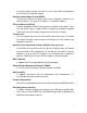
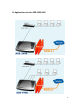
Chapter 1 Introduction 1.1 Introducing the ADE-3400/4400 Planet ADE-3400/4400 ADSL 2/2+ Router is an “all-in-one” unit, combining an ADSL 2/2+ modem, NAT router and Ethernet switch (ADE-4400), providing things you need to get the PCs/laptops on your network connected to the Internet over your ADSL or more ADSL 2+ high speed broadband connection. ADE-3400 is a single port ADSL 2/2+ modem router and ADE-4400 is an ADSL 2/2+ router with 4-port 10/100Mbps Ethernet switch.
It supports downstream rates of up to 24 Mbps and upstream rates of up to 1 Mbps. It is compliant with Multi-Mode standard (ANSI T1.413, Issue 2; G.dmt (G.992.1); G.lite (G992.2), G.hs (G994.1), G.dmt.bis (G.992.3), G.dmt.bisplus (G.992.5). Fast Ethernet Switch (ADE-4400) A 10/100Mbps fast Ethernet switch is built in with automatic switching between MDI and MDI-X for 10Base-T and 100Base-TX ports.
conversion request packet from the PC to this router will be forwarded to the real DNS in the outside network. Dynamic Domain Name System (DDNS) The Dynamic DNS service allows you to alias a dynamic IP address to a static hostname. This dynamic IP address is the WAN IP address. PPP over Ethernet (PPPoE) Provides embedded PPPoE client function to establish a connection. Users can get greater access speed without changing the operation concept, sharing the same ISP account and paying for one access account.
1.
Chapter 2 Product Information 2.1 Package Contents ADE-3400/4400 ADSL 2/2+ Router CD-ROM containing the online manual Quick Installation Guide RJ-11 cable RJ-45 cable Power adapter (ADE-3400: 9V AC, 1A) / (ADE-4400: 12V DC, 1A) 2.
ADE-4400 LED Indicator LED Meaning 1 PPP : Lit steady when there is a PPPoA / PPPoE connection. 2 ADSL: Lit when successfully connected to an ADSL DSLAM (“linesync”). 3 Lit when connected to an Ethernet device. Green for LAN (1-4 100Mbps; Orange for 10Mbps. Blinking when data is for ADE-4400): Transmitted / Received. 4 SYS : Lit when the system is ready. 5 PWR : Lit when power is ON.
2.3 The Rear Ports ADE-3400 ADE-4400 Rear panel Port and Button Definition Port 1 9V AC: ADE-3400 12V DC: ADE-4400 2 RESET 3 LAN 4 ADSL Meaning Connect the supplied power adapter to this jack. After the device is powered on, press it to reset the device or restore to factory default settings. 0-3 seconds: reset the device 6 seconds above: restore to factory default settings (this is used when you can not login to the router, e.g.
2.4 Cabling One of the most common causes of problems is bad cabling or ADSL line(s). Make sure that all connected devices are turned on. On the top of the product is a bank of LEDs. Verify that the LAN Link and ADSL line LEDs are lit. If they are not, verify that you are using the proper cables. Ensure that all other devices connected to the same telephone line as your Planet router (e.g.
Chapter 3 Installation The router can be configured with your web browser. A web browser is included as a standard application in the following operating systems: Windows 98/Me/NT /2000/XP, etc. The product provides a very easy and user-friendly interface for configuration. 3.1 Before Configuration PCs must have an Ethernet interface installed properly and be connected to the router either directly or through an external repeater hub.
double-click on Network Connections 2. Double-click Local Area Connection. 3. In the Local Area Connection Status window, click Properties. 4. Select Internet Protocol (TCP/IP) and click Properties. 5. Select the Obtain an IP address automatically and the Obtain DNS server address automatically radio buttons. 6. Click OK to finish the configuration.
Configuring PC in Windows 2000 1. Go to Start / Settings / Control Panel. In the Control Panel, double-click on Network and Dial-up Connections. 2. Double-click Local Area Connection. 3. In the Local Area Connection Status window click Properties.
4. Select Internet Protocol (TCP/IP) and click Properties. 5. Select the Obtain an IP address automatically and the Obtain DNS server address automatically radio buttons. 6. Click OK to finish the configuration. Configuring PC in Windows 98/Me 1. Go to Start / Settings / Control Panel. In the Control Panel, double-click on Network and choose the Configuration tab. 2. Select TCP/IP ->NE2000 Compatible, or the name of your Network Interface Card (NIC) in your PC.
3. Select the Obtain an IP address automatically radio button. 4. Then select the DNS Configuration tab. 5. Select the Disable DNS radio button and click OK to finish the configuration.
Configuring PC in Windows NT4.0 1. Go to Start / Settings / Control Panel. In the Control Panel, double-click on Network and choose the Protocols tab. 2. Select TCP/IP Protocol and click Properties. 3. Select the Obtain an IP address from a DHCP server radio button and click OK.
3.2 Factory Default Settings Before configuring your ADSL router, you need to know the following default settings. Web Interface: User name: admin Password: admin LAN Device IP Settings: IP Address: 192.168.1.254 Subnet Mask: 255.255.255.0 ISP setting in WAN site: PPPoE DHCP server: DHCP server is enabled. Start IP Address: 192.168.1.
3.3 LAN and WAN Port Addresses The parameters of LAN and WAN ports are pre-set in the factory. The default values are shown below. 3.4 Information from your ISP Before configuring this device, you have to check with your ISP (Internet Service Provider) what kind of service is provided such as PPPoE, PPPoA, RFC1483, or IPoA. Gather the information as illustrated in the following table and keep it for reference.
3.5 Configuring with your Web Browser Open your web browser, enter the IP address of your router, which by default is 192.168.1.254, and click “Go”, a user name and password window prompt will appear. The default user name and password are “admin” and “admin”.
Chapter 4 Configuration At the configuration homepage, the left navigation pane where bookmarks are provided links you directly to the desired setup page, including: Wizard Setup (wizard setup) Advanced Setup (Password, LAN, WAN, Wireless, NAT, Security, Dynamic DNS, Time Zone, Remote Management Control, UPnP) Static Route(Current Route) Maintenance (System Status, DHCP Table, Diagnostic, Firmware) Logout.
Mode: Select Routing (default). If your ISP allows multiple computers to share an Internet account. Otherwise select Bridge. Encapsulation: Select the encapsulation type your ISP uses from the Encapsulation drop-down list box. Choose vary depending on what you select in the Mode field. If you select Bridge in the Mode field, select 1483 Bridged IP. If you select Routing in the Mode field, select PPPoA, 1483 Bridged IP, 1483 Router IP, or PPPoE.
Service Name: Type the name of your PPPoE service here. User Name: Enter the user name exactly as your ISP assigned. Password: Enter the password associated with the user name above. IP Address: Type your ISP assigned IP address in the IP Address text box below. Connection: Select Connect on Demand when you don't want the connection up all the time and specify an idle time-out (in seconds) in the Max. Idle Timeout field.
from the drop-sown list box. Refer to the NAT chapter (4.2.4) for more details. 4.1.3 1483 Routed IP Select 1483 Router IP from the Encapsulation drop-down list box in the first wizard screen to display the screen as shown. IP Address: Type your ISP assigned IP address in the IP Address text box below. Network Address Translation: Select None, Many to One or Many to Many from the drop-sown list box. Refer to the NAT chapter (4.2.4) for more details. 4.1.
IP Address: Type your ISP assigned IP address in the IP Address text box below. Subnet Mask: Enter a subnet mask in dotted decimal notation. Gateway: You must specify a gateway IP address (supplied by your ISP) when you use 1483 Bridged IP in the Encapsulation field in the previous screen. Network Address Translation: Select None, Many to One or Many to Many from the drop-sown list box. Refer to the NAT chapter (4.2.4) for more details. 4.1.
User Name: Enter the user name exactly as your ISP assigned. Password: Enter the password associated with the user name above. IP Address: Type your ISP assigned IP address in the IP Address text box below. Connection: Select Connect on Demand when you don't want the connection up all the time and specify an idle time-out (in seconds) in the Max. Idle Timeout field. Network Address Translation: Select None, Many to One or Many to Many from the drop-sown list box. Refer to the NAT chapter (4.2.
4.1.6 Wizard Setup Configuration If you want to change your ADE-3400/4400 LAN settings, click Change LAN Configuration to display the screen as shown next.
LAN IP Address: Enter the IP address of ADE-3400/4400 in dotted decimal notation, for example, 192.168.1.254 (factory default). LAN Subnet Mask: Enter a subnet mask in dotted decimal notation. DHCP Server: From the DHCP Server drop-down list box, select On to allow ADSL Router to assign IP addresses, an IP default gateway and DNS servers to computer systems that support the DHCP client. Select Off to disable DHCP server.
4.2 Advanced setup 4.2.1 Password In factory setting, the default password is admin. You can change the default password to ensure that someone cannot adjust your settings without your permission. Every time you change your password, please record the password and keep it at a safe place.
Old Password: Type the default password or the existing password you use to access the system in this field. New Password: Type the new password in this field Retype to confirm: Type the new password again in this field. 4.2.2 LAN Click LAN to open the following screen.
DHCP: If set to Server, your ADE-3400/4400 can assign IP addresses, an IP default gateway, and DNS servers to Windows 95/NT and other systems that support the DHCP client. If set to None, the DHCP server will be disabled. If set to Relay, the ADE-3400/4400 acts as a surrogate DHCP server and relays DHCP requests and responses between the remote server and the clients. Enter the IP address of the actual, remote DHCP server in the Remote DHCP Server field in this case.
4.2.3 WAN Setup A WAN (Wide Area Network) is an outside connection to another network or the Internet. It allows the user to set the configuration for the WAN/ADSL ports. To change ADE-3400/4400 WAN remote node settings, click WAN.
Half Bridge Name: Enter the name of your Internet Service Provider Mode: Select Routing (default) or Bridge Encapsulation: Select Bridge in the Mode field and select either PPPoA or RFC 1483. Select Routing in the Mode field and select PPPoA, RFC 1483, ENET ENCAP, or PPPoE. Multiplex: Select the method of multiplexing used by your ISP. Choose VC or LLC.
Virtual Circuit ID: VPI and VCI define a virtual circuit. VPI: The valid range for the VPI is 0 to 255 VCI: The valid range for the VCI is 32 to 65535 ATM QoS Type: Select CBR to specify fixed (always-on) bandwidth for voice or data traffic. Select UBR for applications that are non-time sensitive, such as e-mail. Select VBR for burst traffic and bandwidth sharing with other applications.
multiple WAN connections. The LAN traffic is routed to appropriate WAN connections based on the destination IP addresses and Route Table. This eliminates the need for the static NAT session configuration between multiple LAN clients and multiple WAN connections. 4.2.4.1 Selecting the NAT Mode None: Select this radio button to disable NAT Many to One: Select this radio button if you have just one public WAN IP address for your router.
Start Port No.: Enter a port number in this field. End Port No.: Enter a port number in this field. IP Address: Enter your server IP address in this field. 4.2.4.3 Configuring Address Mapping To change your ADE-3400/4400 address mapping settings, click NAT, Select Many to Many and click Edit Details to open the following screen.
Local Start IP: This is the starting Inside Local IP Address. Local IP addresses are N/A for Server port mapping. Local End IP: This is the end Inside Local IP Address (ILA). If your rule is for all local IP addresses, then enter 0.0.0.0 as the Local Start IP address and 255.255.255.255 as the Local End IP address. This field is N/A for One-to-one and Server mapping types. Global Start IP: This is the starting Inside Global IP Address (IGA). Enter 0.0.0.0 here if you have a dynamic IP address from your ISP.
the NAT to be accessible to the outside world. 4.2.4.4 Editing an Address Mapping Rule To edit an address mapping rule, click the rule’s link in the NAT Address Mapping Rules screen to display the screen shown next. Type: 1-1: One-to-one mode maps one local IP address to one global IP address. Note that port numbers do not change for the One-to-one NAT mapping type. M-1: Many-to-One mode maps multiple local IP addresses to one global IP address. This is equivalent to Many to One (i.e.
Global Start IP: This is the starting Inside Global IP Address (IGA). Enter 0.0.0.0 here if you have a dynamic IP address from your ISP. Global End IP: This is the ending Inside Global IP Address (IGA). This field is N/A for One-to-one, Many-to-One and Server mapping types. Server Mapping Set: Only available when Type is set to Server. Select a number from 1 to 10 from the drop-down menu to choose a server set from the NAT - Address Mapping Rules screen.
The Dynamic DNS function allows you to alias a dynamic IP address to a static hostname, allowing users whose ISP does not assign them a static IP address to use a domain name. This is especially useful for hosting servers via your ADSL connection, so that anyone wishing to connect to you may use your domain name. It rather than uses your dynamic IP address which changes from time to time. This dynamic IP address is the WAN IP address of the router, which is assigned to you by your ISP.
Network Time Protocol (SNTP) to get the current time from an SNTP server outside your network. Choose your local time zone. After a successful connection to the Internet, the router will retrieve the correct local time from the SNTP server you have specified. If you prefer to specify an SNTP server other than those in the drop-down list, simply enter its IP address as shown above. Your ISP may provide an SNTP server for you to use.
Time Server IP Address: Enter the IP address of your time server. Check with your ISP/network administrator if you are unsure of this information. Time Zone: Choose the time zone of your location. This will set the time difference between your time zone and Greenwich Mean Time (GMT). Daylight Savings: Select this option if you use daylight savings time.
4.2.8 Remote Management Remote management allows you to determine which services/protocols can access which ADE-3400/4400 interface from which computers. You can configure the router for remote Telnet access or upload and download router firmware and configuration files using FTP. To use this feature, your computer must have an FTP client. You can use the ADE-3400/4400’s embedded web configuration for configuration and file management.
advantages for users running NAT routers through UPnP NAT Traversal, and on supported systems makes tasks such as port forwarding much easier by letting the application control the required settings, removing the need for the user to control advanced configuration of their device. Both the user’s Operating System and the relevant application must support UPnP in addition to the router.
Step 3. In the Communications window, select the Universal Plug and Play check box in the Components selection box. Step 4. Click OK to go back to the Add/Remove Programs Properties window and click Next. Step 5. Restart the computer when prompted. Follow the steps below to install the UPnP in Windows XP. Step 1. Click Start and Control Panel. Step 2. Double-click Network Connections. Step 3.
and select Optional Networking Components …. The Windows Optional Networking Components Wizard window displays. Step 4. Select Networking Service in the Components selection box and click Details. Step 5. In the Networking Services window, select the Universal Plug and Play check box. Step 6. Click OK to go back to the Windows Optional Networking Component Wizard window and click Next.
Auto-discover Your UPnP-enabled Network Device Step 1. Click start and Control Panel. Double-click Network Connections. An icon displays under Internet Gateway. Step 2. Right-click the icon and select Properties. Step 3. In the Internet Connection Properties window, click Settings to see the port mappings there were automatically created.
Step 4. You may edit or delete the port mappings or click Add to manually add port mappings. Step 5. Select Show icon in notification area when connected option and click OK.
Step 6. Double-click on the icon to display your current Internet connection status. Web Configurator Easy Access With UPnP, you can access the web-based configurator on the ADE-3400/4400 without finding out the IP address of the ADE-3400/4400 first. This is helpful if you do not know the IP address of the ADE-3400/4400. Follow the steps below to access the web configurator. Step 1. Click Start and then Control Panel. Step 2. Double-click Network Connections. Step 3.
Step 4. An icon with the description for each UPnP-enabled device displays under Local Network. Step 5. Right-click on the icon for your ADE-3400/4400 and select Invoke. The web configurator login screen displays.
Step 6. Right-click on the icon for your ADE-3400/4400 and select Properties. A properties window displays with basic information about the ADE-3400/4400. 4.3 Static Route 4.3.1 Current Route If you have another router with a LAN-to-LAN connection, you may create a static routing on the router that is the gateway to Internet. Active: Whether the connection is currently active.
Destination IP:This is the destination subnet IP address. Subnet Mask:It is the destination IP address based on above destination subnet IP. Gateway IP : This is the gateway IP address to which packets are to be forwarded. Metric:It represents the cost of transmission for routing purposes. The number need not be precise, but it must be between 1 to 15. Private:This parameter determines if the Prestige will include the route to the remote node in its RIP broadcasts.
4.4.1 System Status System Status: System Name: This is the name of the router. It is for identification purposes. RAS F/W Version: This is the firmware version and the date created. DSL FW Version: This is the DSL firmware version associated with your router. Standard: This is the standard that the router is using.
IP Address: This is the WAN port IP address IP Subnet Mask: This is the WAN port IP subnet mask. Default Gateway: This is the IP address of the default gateway VPI/VCI: This is the Virtual Path Identifier and Virtual Channel Identifier that you entered in the first Wizard screen. LAN Information: MAC Address: This is the MAC (Media Access Control) or Ethernet address IP Address: This is the LAN port IP address. IP Subnet Mask: This is the LAN port IP subnet mask.
System up Time: This is the elapsed time the system has been up. CPU Load: This field specifies the percentage of CPU utilization. WAN Port Statistics: This is the WAN port. Link Status: This is the status of your WAN link. Transfer Rate: This is the transfer rate in kbps. Upstream Speed: This is the upstream speed of the router. Downstream Speed: This is the downstream speed of the router. Node-Link: This field displays the remote node index number and link type.
shows the port speed and duplex setting. TxPkts: This field displays the number of packets transmitted on this port. RxPkts: This field displays the number of packets received on this port. Errors: This field displays the number of error packets on this port. Tx B/s: This field displays the number of bytes transmitted in the last second. Rx B/s: This field displays the number of bytes received in the last second. Up Time: This field displays the elapsed time this port has been up.
4.4.4.1 Diagnostic-General TCP/IP Address: Type the IP address of a computer that you want to ping in order to test a connection. Ping: Click this button to ping the IP address that you entered. Reset System: Click this button to reboot the ADE-3400/4400. A warning dialog box is displayed and asking you if you're sure you want to reboot the system. Click OK to proceed. 4.4.4.
Reset ADSL Line: Click this button to reinitialize the ADSL line. The large text box above then displays the progress and results of this operation ATM Status: Click this button to view ATM status. ATM Loopback Test: Click this button to start the ATM loopback test. Make sure you have configured at least one PVC with proper VPIs/VCIs before you begin this test. The ATM loopback test is useful for troubleshooting problems with the DSLAM and ATM network.
copy the firmware to your local environment first. Press the “Browse…” button to specify the path of the firmware file. Then, click “Upload” to start upgrading. When the procedure is completed, ADE-3400/4400 will reset automatically to make the new firmware work. File Path: Type in the location of the file you want to upload in this field or click Browse ...to find it. Browse...: Click Browse... to find the .ras file you want to upload. Remember that you must decompress compressed (.
4.4.6 Restart Click Restart with option Current Settings to reboot your router (and restore your last saved configuration). If you wish to restart the router using the factory default settings (for example, after a firmware upgrade or if you have saved an incorrect configuration), select Factory Default Settings to reset to factory default settings.
4.5 Logout To exit the router’s web interface, choose Logout. Please ensure that you have saved the configuration settings before you logout. Be aware that the router is restricted to only one PC accessing the configuration web pages at a time. Once a PC has logged into the web interface, other PCs cannot get access until the current PC has logged out of the web interface. If the previous PC forgets to logout, the second PC can access the page after a user-defined period, by default 3 minutes.
Chapter 5 Troubleshooting If the ADSL Router is not functioning properly, you can refer first to this chapter for simple troubleshooting before contacting your service provider. This could save your time and effort but if the symptoms persist, then consult your service provider.
Problems with the LAN Interface 66