
User's Manual
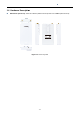
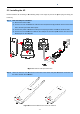
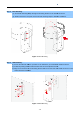

1.4.1 The Bottom Panel –
Port
The Bottom panel provides
the physical connectors connected to the power adapter and any other network
device. Figure 1-5 shows the bottom
Bottom Panel
Figure
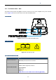
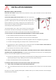
PoE Warning Label
Hardware Interface Definition
Object
Description
Antenna Connectors
2
RP
Passive PoE LAN Port
10/100Mbps RJ45 port,
Passive
Pin
Pin 4, 5
Pin 7, 8
NOTE: Please use the 24VDC Passive PoE only (included)
User Manual of
WAP
-13-
Port
the physical connectors connected to the power adapter and any other network
panel of the WAP-500N/WBS-500N.
Figure
1-3 Bottom Panel (WAP-500N/WBS-500N)
Figure 1-4 PoE Warning Label
Description
RP
-SMA (Female) antenna connectors
10/100Mbps RJ45 port,
auto MDI/MDI-X
Passive
PoE/PD supported, 24VDC In
assignment:
Pin 4, 5
(+)
Pin 7, 8
(-)
NOTE: Please use the 24VDC Passive PoE only (included)
WAP
-500N/WBS-500N
the physical connectors connected to the power adapter and any other network
NOTE: Please use the 24VDC Passive PoE only (included)
.