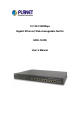
0/100/1000Mbps Gigabit Ethernet Web-manageable Switch GSW-1402S User’s Manual
Trademarks Copyright PLANET Technology Corp. 2003. Contents subject to revision without prior notice. PLANET is a registered trademark of PLANET Technology Corp. to their respective owners. All other trademarks belong Disclaimer PLANET Technology does not warrant that the hardware will work properly in all environments and applications, and makes no warranty and representation, either implied or expressed, with respect to the quality, performance, merchantability, or fitness for a particular purpose.
TABLE OF CONTENTS CHAPTER 1 INTRODUCTION ..............................................................................1 1.1 CHECKLIST .........................................................................................................................1 1.2 ABOUT THE SWITCH ............................................................................................................1 1.3 FEATURES ..............................................................................................................
APPENDIX A ..................................................................................................................25 A.1 SWITCH‘S RJ-45 PIN ASSIGNMENTS..................................................................................25 A.2 10/100MBPS, 10/100BASE-TX ........................................................................................25 A.3 RJ-45 CABLE PIN ASSIGNMENT..........................................................................................
Chapter 1 INTRODUCTION 1.1 Checklist Check the contents of your package for following parts: l GSW-1402S. l CD-ROM. l Quick Installation Guide l Power cord. l 19” rack mount brackets. l RS-232 cable. If any of these pieces are missing or damaged, please contact your dealer immediately, if possible, retain the carton including the original packing material, and use them against to repack the product in case there is a need to return it to us for repair. 1.
1.4 Specifications Network Ports 14 x RJ-45, 10/100/1000Base-T Module slot 2, 1000Base-T, 1000Base-SX, 1000Base-LX Modes Half and Full Duplex, auto-negotiation Console 1 x RS-232 DB-9 MAC address table size 4k Switch Fabric 32Gbps Transmission method Store-and-forward Packet Buffer Memory 272K Bytes 14880pps @ 10Mbps Packet Forwarding Rate (64bytes) 148800pps @ 100Mbps 1488000pps @ 1000Mbps VLAN Support IEEE 802.1Q VLAN, up to 255 groups.
Chapter 2 Hardware Description This product series provide three different operating speed – 10Mbps, 100Mbps, and 1000Mbps in the same switch and automatically distinguish the speed of incoming connection. This section describes the hardware features of these Switches. For easier management and control of the switch, familiarize yourself with its display indicators, and ports. Front panel illustrations in this chapter display the unit LED indicators.
Power Notice: 1. The device is a power-required device, it means, it will not work till it is powered. If your networks should active all the time, please consider using UPS (Uninterrupted Power Supply) for your device. It will prevent you from network data loss or network downtime. 2. In some area, installing a surge suppression device may also help to protect your switch from being damaged by unregulated surge or current to the Switch or the power adapter. 2.3 Hardware Installation 2.3.
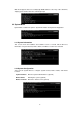
Chapter 3 Console management 3.1 Connect To PC RS-232 serial cable Prepare a RS-232 serial cable. Attach the 9-pin female connector to the male connector on the switch. Plug the other side of this cable to your PC. Hyper Terminal In Windows 95/98/2000/XP, launch “HyperTerminal”, create a new connection, and adjust settings as below: 3.2 Main Menu Power on the switch; launch the new terminal program you just set up. Press “Enter” key, then login screen appears as below.
Main menu appears after successfully login GSW-1402S. To enter any of the submenus, simply type the number after the command prompt. 3.3 System Menu System Menu contains two options: System Information and System Configuration. 3.3.1 System Information This screen shows the hardware and software versions of current switch. Moreover, information of System Contact, Device Name, and Device Location also included. 3.3.
3.4 Management Setup Menu Management Setup Menu contains three options: Network Configuration, Console Port Status Display, and Management Features Control. 3.4.1 Network Configuration To display the current network settings of switch, select 1 from Management Setup Menu. This screen also allows user to modify these settings including IP address, Subnet Mask, and Default Gateway.
3.4.3.2 Telnet Capability Select 2 from Management Features Control Menu. To enable Telnet management interface, select 1. To disable Telnet management interface, select 2. 3.5 Device Control Menu Device Control Menu sets up the advanced functions of GSW-1402S include Port Configuration, VLAN, Port Mirror, and Port Aggregation (Trunk). 3.5.1 Port Status/Configuration From Device Control Menu, select 1 to enter Port Status/Configuration Menu.
3.5.2 IEEE802.1Q TAG VLAN The VLAN is a group of ports that may spread around the network but communicate as though they belong to one subnet. By using IEEE802.1Q compliant VLAN, all ports can be reorganized into separate broadcast domains for security reasons and reduce bandwidth occupation instead of using routers to divide whole network into subnets.
3.5.2.3 VLAN Static Entry Created To create a static VLAN entry, select 3 from IEEE802.1Q TAG VLAN Menu. Enter the information of VLAN ID, name, and active status. 3.5.2.4 VLAN Static Entry Modification To modify an existing VLAN entry, select 4 from IEEE802.1Q TAG VLAN Menu. Choose which VLAN you want to modify, then change the data in next screen. 3.5.2.5 VLAN Static Entry Delete To delete an existing VLAN entry, select 5 from IEEE802.1Q TAG VLAN Menu. Choose which VLAN you want to delete.
3.5.3.1 Mirror Function To set the Mirror Function active or inactive, select 1 from Port Mirror Menu. 3.5.3.2 Choose Sniffer Port To change current sniffer port, select 2 from Port Mirror Menu. Then enter the desired port number. 3.5.3.3 Choose Monitored Port To change current monitored port, select 3 from Port Mirror Menu. Then enter the desired port numbers. If you want to enter two numbers, please use a comma between numbers. 3.5.
However, before making trunk connections between switches, pay attention to: 1. The ports at both ends of a Port Aggregation connection must be configured as Aggregation Ports. 2. The ports at both ends of a Port Aggregation connection must have the same port properties, including Speed, Duplex mode. 3. All the ports of a Port Aggregation must be treated as an integer when added to/deleted from a VLAN. 4. Before connecting cables between switches, enable the Pot Aggregation to avoid looping. 5.
3.7.2 Default Factory Reset To reset switch to factory default parameters, select 2 from System Utility Menu. Then click “Y” to reset GSW-1402S. 3.7.3 Timeout Interval Setup The default timeout value of GSW-1402S is 5 minutes. To modify timeout value, select 3 from System Utility Menu, then enter the desired timeout value. 3.7.4 TFTP Download This menu enables user to download firmware via TFTP and upgrade GSW-1402S. To enter TFTP Menu, select 4 from System Utility Menu.
3.7.5.1 Modify Ping Count To modify the ping packet count number, select 1 from Ping Menu. Type a count number from 1 to 1000, or type 0 for an infinite packet count. 3.7.5.2 Modify Ping Target IP To change the IP address of target host, select 2 from Ping Menu. Then enter the correct IP. 3.7.5.3 Start Ping After all above parameters are properly configured, select 3 from Ping Menu to start ping test. System will show the test result as follow. 3.7.
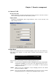
4. Web management 4.1 Start A Web Browser Session The Web Interface of GSW-1402S is coded by Java Applet and running on the JavaTM Virtual Machine (JVM) version 1.3.1 platform. You should configure the management station with an IP address and subnet mask compatible with GSW-1402S for accessing it. Also, the management station should be well configured and connected to Internet for automatically downloading (upgrading) the suitable JVM through Internet from http://java.sun.com.
4.2.1 Save This button enables user to save current settings to NVRAM. After click on it, the following message box appears. Click “Yes” to save settings, click “No” to abort. 4.2.2 Default This button enables user to reset GSW-1402S to factory default values. After click on it, the following message box appears. Click “Yes” to reset switch, click “No” to abort. 4.2.3 Reboot This button enables user to reboot switch without unplug the power cord. After click on it, the following message box appears.
4.2.4 Ping This button enables user to use ping function. After click on it, the following message box appears. Enter information in Ping Count field and Target IP Address field, then click “Start”. The result will be shown in the same message box after test is done. 4.2.5 Telnet This button enables user to access GSW-1402S through Telnet. After click on it, the Hyper Terminal program will be activated and directly connect to switch. 4.2.
4.4 Port Page There are two tabs in Port Page: Information and Configuration. Please refer to section 3.5.1 Port Status/Configuration for further details. 4.4.1 Port Setting Duplicate This function enables user to duplicate similar settings to all ports at one time. Please follow the procedures below: 1. Click “Configuration” tab in Port Page. 2. Click “Duplicate” button, the dialogue screen appears. 3. 4. 5. 6. 7. 8.
4.5 VLAN Page There are three tabs in VLAN Page: VLAN Static List, VLAN Static Table, and VLAN Port Configuration. Please refer to section 3.5.2 IEEE802.1Q TAG VLAN for further details. 4.5.1 VLAN Static List This screen is used to Add / Remove / Modify VLAN and up to 255 groups. The VLAN groups that have been created are all listed here. 4.5.1.1 To Create A New VLAN Group 1. Specify the name for the new VLAN group (VLAN name is only used for identification). 2.
4.5.2.1 To Add Member Ports 1. Click the “VLAN ID” combo box and select a VLAN you want new ports to join in. 2. Select ports (press Shift/Ctrl key for selecting multi ports) in the “Non-Member” column. 3. Click <> button to delete selected ports. Note: 1.
4.6 Port Aggregation Page This screen includes information of Aggregation Group number, Member Port, and Group Status. Please refer to section 3.5.4 Port Aggregation for further details. To activate an Aggregation Group, check the box of Aggregation Group in the Status Enable column and press “Apply”. 4.7 Mirror Page This screen shows Mirror status, Monitored port number, and Sniffer port number. Please refer to section 3.5.3 Mirror for further details.
5 Switch Operation 5.1 Address Table The Switch is implemented with an address table. This address table composed of many entries. Each entry is used to store the address information of some node in network, including MAC address, port no, etc. This information comes from the learning process of Switch. 5.2 Learning When one packet comes in from any port, the Switch will record the source address, port no. and the other related information in address table.
the modes and speeds at the second of both device is connected and capable of, Both 10Base-T and 100Base-TX devices can connect with the port in either Half- or Full-Duplex mode. 1000Base-T and 1000Base-SX can only connect in Full-duplex mode.
6. Troubleshooting This chapter contains information to help you solve problems. If GSW-1402S is not functioning properly, make sure the Switch was set up according to instructions in this manual. The Link LED is not lit Solution: Check the cable connection and remove duplex mode of the Giga Switch Some stations can not talk to other stations located on the other port Solution: The address table may contain older information than of the address table of that node.
APPENDIX A A.1 Switch’s RJ-45 Pin Assignments 1000Mbps, 1000Base T Contact MDI MDI-X 1 BI_DA+ BI_DB+ 2 BI_DA- BI_DB- 3 BI_DB+ BI_DA+ 4 BI_DC+ BI_DD+ 5 BI_DC- BI_DD- 6 BI_DB- BI_DA- 7 BI_DD+ BI_DC+ 8 BI_DD- BI_DC- Implicit implementation of the crossover function within a twisted-pair cable, or at a wiring panel, while not expressly forbidden, is beyond the scope of this standard. A.2 10/100Mbps, 10/100Base-TX Contact MDI MDI-X 1 1 3 2 2 6 3 3 1 6 6 2 A.