Planar LT3200 Owner Manual LT3200 Owner Manual 1|Page
This manual is designed for use with the Planar® LT3200 LookThru™ open frame transparent display. Information in this document has been carefully checked for accuracy; however, no guarantee is given to the correctness of the contents. The information contained in this document is subject to change without notice. This document contains proprietary information that is protected by copyright. All rights are reserved.
Table of Contents I. PRECAUTIONS ............................................................................................................................ 4 II. LT3200 PRODUCT DESCRIPTION ...........................................................................................5 III. LT3200 DISPLAY COMPONENTS ............................................................................................ 6 IV. PRODUCT ARCHITECTURE .....................................................................
I. Precautions and Warnings To maximize the life and safe use of your Planar product, always be sure to follow the warnings and precautions in this product guide. Important Instructions: 1. Read, retain, and heed all warnings and instructions. 2. You must follow all National Electrical Code regulations. In addition, be aware of local codes and ordinances when installing your system. Do: Keep in mind this is an open frame display component.
II. LT3200 Product Description The Planar LT3200 is a high performance open frame transparent display for use indoors in a customer-designed enclosure. Possible digital signage applications include various retail, marketing and other digital showcase uses.
III.
LC3200 Display Components, cont’d Top, Backside and Edge Views of the Driver Box Cable Grommet Driver Box Lid Fasteners Top View Power Switch Backside View DisplayPort HDMI 48V Input from Power Brick Edge View LT3200 Owner Manual 7|Page Power Switch
IV.
V. Designing an Enclosure for your LT3200 The LT3200 open frame display will provide best in class transparent display performance, but the enclosure design is a critical contributor to the appearance and operation of the full display assembly. We encourage our customers to be creative in designing their presentation configuration using the LT3200. To achieve optimum results, we recommend the following: - Orientation: the display can be used in portrait, landscape or countertop (horizontal) mode.
VI. Connecting the Driver Box The LT3200 is shipped with the wiring bundle disconnected from the Driver Box so the free end of the bundle can be routed in the enclosure as part of the assembly process. This section describes how to connect the wiring bundle to the Driver Box. You will need a small (#1) Phillips screwdriver. Note: It is important to follow the instructions carefully and observe safe ESD practices, especially if the assembly is taking place away from a grounded workbench.
4- Locate the video connector in cable assembly as shown in photo 4 at right. 5- Orient the video plug as seen in Photo 5A. Insert the edge into its socket on the video board. Align the connector parallel to the socket and gently slide the connector into the socket (Photo 5B). Using steady pressure between thumb and fingernail of index finger, seat the connector. A properly inserted connector will have the backside of the connector located parallel to the socket.
7- Once the LED connector, the two ground connections, and the video connector have been attached, position the rubber grommet into the slot in the box as shown in Photo 7. 8- Position the lid over the lower half of the box as shown, making sure the tab in the lid (arrow in Photo 8) captures the grommet. 9- Refasten the four Phillips screws to secure the Driver Box cover. The assembled Driver Box is shown in Photo 9 at right.
VII. Presentation of Your Material using the LT3200 You should experiment with placement of the objects to be displayed in the LT3200 to optimize their appearance and interaction with your video content. You will find that the brightness of display box and the legibility of the screen content can be affected by the color of objects placed in the display box. For best results we suggest avoiding large areas of dark colors inside the display box.
VIII.
Driver Box Drawing LT3200 Owner Manual 15 | Page
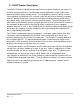
Troubleshooting A properly-functioning LT3200 will show a “splash screen” when power is first applied. If a suitable video source is attached, the screen will then display whatever video image is being sent to the LT3200 shortly after the splash screen appears. Note that when power is applied you should also see light from the LEDs located around the perimeter of the AMLCD screen. When power is being supplied to the LT3200 power supply, the indicator light on the power brick will glow.
LT3200 Specifications This section contains specifications for the LT3200 display. Product Name LT3200 Planar Part Number 997‐6868‐00 Viewable Size 31.25" diagonal (27.3” x 15.2”) Viewing Angle (Typical) 178° Horizontal and Vertical Response Time (G‐to‐G, Typical) 8 msec Brightness (Typical) Dependant on customer enclosure design Native Display Resolution 1366 x 768 Aspect Ratio 16:9 Color Palette 16.7 million colors Pixel Pitch 0.
Power Supply External AC adapter, 48V DC Power Requirements 100‐240 VAC (50/60 Hz) Power Consumption 125W Module Mounting Built‐in mounting bracket, see outline drawing Service and Support 3‐Year Warranty Product Approvals NRTL Listed, FCC‐Class A, CE, RoHS Environmental ‐ Operating Temperature 0° to 40°C Environmental ‐ Operating Temperature ‐10° to 50°C In the Box LT3200 32" LookThru LCD module, Driver Box, Power Brick and Cord, HDMI Cable, User’s Manual LT3200 Owner Manual 18 | Page
Graphics Input Compatibility The LCD monitor has been tested to synchronize to, and scale the following digital signal graphics inputs and generate a stable display that has a similar geometry.