
user manual
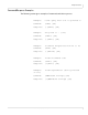
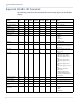
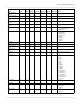
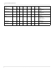
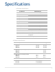
Table Of Contents
- Table of Contents
- Introduction
- Installing a Planar UltraRes Display
- LCD Installation
- Installing the UltraRes Control Software
- Using the UltraRes Control Software
- UltraRes Dimensions
- Display Dimensions - Front and Side Views
- Display Dimensions - Rear View
- Landscape Wall Mounts - Front View
- Landscape Wall Mounts - Sides Views
- Portrait Wall Mounts - Front View
- Portrait Wall Mounts - Sides Views
- Optional Pedestal Mount - Front View
- Optional Pedestal Mount - Top and Bottom Views
- Optional Pedestal Mount - Single and Double Sided
- Planar UltraRes Remote Monitoring Software
- RS232 Communication
- RS232 Commands
- Command Format
- Response Format
- Supported UltraRes 4K Commands
- Specifications
- Troubleshooting During Installation
- Accessing Planar’s Technical Support Website
- Regulatory Information
- Index
Supported UltraRes 4K Commands
78 Planar UltraRes User Manual
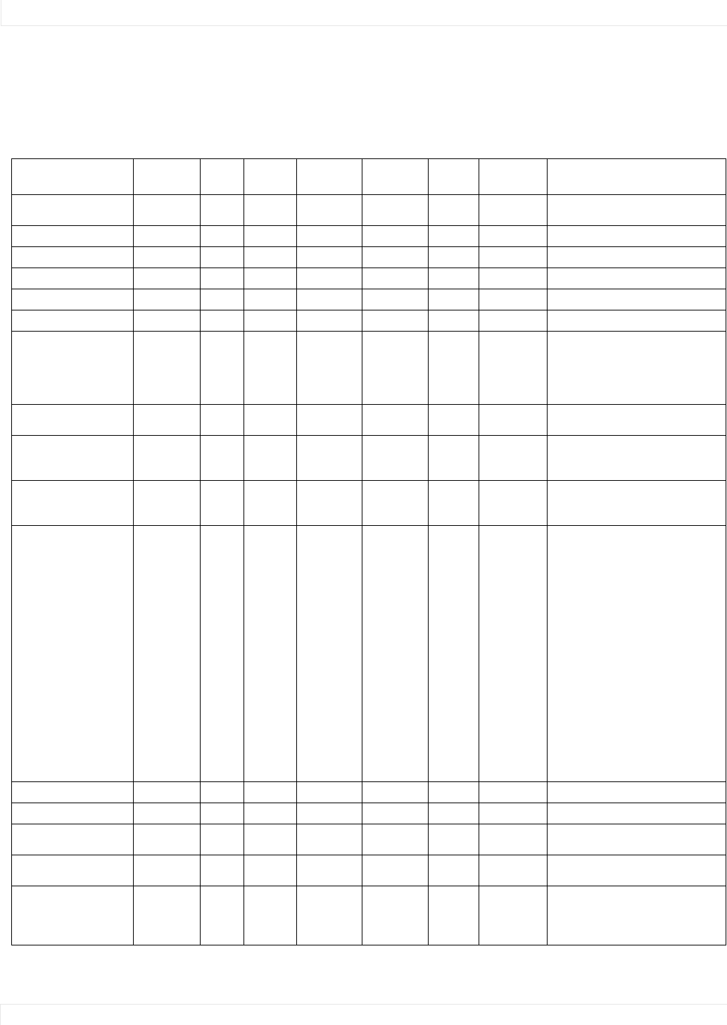
Supported UltraRes 4K Commands
The following section lists the commands that are currently support on the UltraRes
display.
Setting
Command
Code
Read/
Write Inc/Dec MinValue MaxValue String?
Password
Protected? Notes
Auto Power Off Enable APE R/W No 0 1 No No 0 = Off
1 = On
Auto Power Off Timer APT R/W No 1 60 No No Value is in minutes
Backlight BKL R/W No 1 15 No No
Blank Screen Blue BSB R/W Yes 0 255 No No
Blank Screen Green BSG R/W Yes 0 255 No No
Blank Screen Red BSR R/W Yes 0 255 No No
Color Space CLS R/W No 0 4 No No 0 = REC601
1 = REC709
2 = RGB
3 = RGB Video
4 = Auto
EDID Type EDT R/W No 0 1 No No 0 = Default EDID
1 = 1080p EDID
Error Log 1 EL1 R No N/A N/A Yes No Response contains 50 hex digits
representing the first 25 entries in
the error log
Error Log 2 EL2 R No N/A N/A Yes No Response contains 50 hex digits
representing the second 25 entries
in the error log
Error Code ERR R No 0 TBD No No 0 = None
1 = AC Power Supply 1 Failure
2 = AC Power Supply 2 Failure
3 = AC Power Supplies 1 and 2
Failure
4 = AC Power Supply 3 Failure
5 = AC Power Supplies 1 and 3
Failure
6 = AC Power Supplies 2 and 3
Failure
7 = AC Power Supplies 1, 2 and 3
Failure
8 = AC Power Status Cable
Disconnected
9 = DC Power Supply Failure
10 = FPGA Initialization Failure
11 = Calibration EEPROM Failure
12 = Overtemp
Bottom Frame Delay FDB R/W No 0 2 No No
Top Frame Delay FDT R/W No 0 2 No No
Firmware Upgrade FWU W No N/A N/A No No Action will be performed on any
setting value
Information Boot
Version
IBV R No N/A N/A Yes No
Information Current
Color Space
ICC R No 0 3 No No 0 = REC601
1 = REC709
2 = RGB
3 = RGB Video