PD7130 PD7150 DLP Projector R MEN U ENTE R SOUR CE User's Manual www.PlanarHomeTheater.
Planar Systems, Inc. Corporate Headquarters 1195 NW Compton Drive Beaverton, OR 97006-1992 Planar Customer Support Telephone: US: 1-866-PLANAR1 (866) 752-6271 Outside US: (503) 748-5799 E-mail: PlanarSupport@planar.com Online Technical Library: http://www.planar.
Preface ABOUT THIS MANUAL This manual is designed for use with the PD7130/PD7150 DLP Front Projector. Information in this document has been carefully checked for accuracy; however, no guarantee is given to the correctness of the contents. The information in this document is subject to change without notice. COPYRIGHT © Copyright 2006 This document contains proprietary information protected by copyright. All rights are reserved.
Preface Notices WARNING! To meet FCC requirements, a shielded power cord is required in order to prevent interference. It is essential that only the supplied power cord is to be used. Use only shielded cables to connect I/O devices to this equipment. You are cautioned that changes or modifications not approved by the party responsible for compliance could void your authority to operate the equipment.
PRODUCT DISPOSAL This projector utilizes a tin-lead solder, UHP Lamp containing a small amount of mercury. Disposal of these materials may be regulated due to environmental considerations. Hg Lamp(s) inside this product contain mercury. This product may contain other electronic waste that can be hazardous if not disposed of properly. Recycle or dispose in accordance with local, state, or federal Laws. For more information, contact the Electronic Industries Alliance at WWW.EIAE.ORG.
iv Preface
Contents Contents Preface ................................................................................... i Notices .................................................................................. ii Introduction Package Contents ................................................................. 2 Features ................................................................................ 2 Components ..........................................................................
Factory Reset........................................................................... 31 Appendix Contents Maintenance........................................................................ 34 About the Lamp ................................................................... 35 Caution Concerning the Lamp ................................................. 35 Replacing the Lamp ................................................................. 35 Temperature LED (Temperature Overheat Alarm) .............
Introduction Introduction 1
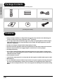
Introduction Package Contents Open the package and ensure that you have the following items: ON POWER OFF SOURCE 1 2 4 3 5 ENTER MENU EXIT USER MEMORY M1 M2 M3 ASPECT GAMMA OS AUTO BLANK LIGHT Remote control User’s Guide Two “AAA” size batteries CD (including this manual) Power cord (By country) RGB Component Cable Features • Newly developed LVDS (Low voltage differential signal) chip eliminates Color Breaking phenomena common with previous generation DLPTM projectors • Use of h
Components Introduction Projector (Front and Top View) Lens shift dial (Vertical) Lens shift dial (Horizontal) POWER (ON/OFF) Press to turn the power on or off. LED Indicator (Green/Red) Green: Standby Red: Overheat ENTER Press to set selected items or adjustments in the menu. SOURCE Press to select the input source. SOURCE Menu Navigation (T,S,W,X) ENTER Press to select menu items. MENU MENU Press to view the OSD menu. Press again to hide the OSD menu.
Source 5: Video/S-Video PB/CB PB/CB PR/CR PR/CR S-VIDEO VIDEO COMP1 PR/CR PB/CB Y RGB-HD DVI-D Source 4: PC RS-232 Terminal for computer and RGB signals. RS-232 12V TRUGGER Y Y PR/CR S-VIDEO PB/CB VIDEO Terminal for Digital Video Interface. COMP2 COMP2 12V TRUGGER RS-232C terminal Firmware upgrade/command control. COMP1 Y 12V Trigger Terminal for screen controlling Source 3: DVI RGB-HD Terminal for connecting video equipment with an S-video or Composite Video terminal.
Remote Control Introduction Power ON and Power OFF ON POWER OFF Press to turn the power on and off. Source 2 Press to select the Component 2 device. SOURCE Source 1 1 Source 4 4 2 3 5 Press to select the PC device. ENTER Menu Navigation (T,S,W,X) Press to set selected items or adjustments in the menu. ENTER MENU EXIT MENU Contrast Press to adjust the display contrast. EXIT USER MEMORY M1 M2 Brightness ASPECT GAMMA OS AUTO BLANK Press to exit the OSD.
Introduction Using the Remote Control Note • The signal from the remote control can be reflected by the screen. When using the remote control: • Do not drop it, or expose it to moisture or high temperature. • The remote control may not function correctly under fluorescent lamps. Operate the projector away from fluorescent lamps. Inserting the Batteries The batteries (two “AAA”) are included in the package. 1 Press down the tab on the cover and slide the cover towards the direction of the arrow.
Connections and Setup Connections and Setup 7
Connecting the Projector to Other Devices Before Setting Up Notes • Before connecting, turn off both the projector and the devices to be connected. After making all connections, turn on the projector first and then the other devices. When connecting a computer, be sure that the computer is the last device turned on, after all connections are made. • Read the operation manuals of the devices to be connected before making connections.
Connecting to Video Equipment Using a S-video or a Composite Video Cable (VIDEO/S-VIDEO) VCR or other video equipment Using a S-video or a composite video cable, a VCR, DVD Player or other video equipment can be connected to the S-VIDEO or VIDEO terminals.
Connecting to Component Video Equipment To analog component output terminal Using a Component Cable (Component 1 or 2) Use a component cable when connecting component video equipment such as DVD players and DTV* decoders to the Component 1 or 2 terminals. *DTV is an umbrella term used to describe the new digital television system.
Connecting Using a DVI-D to HDMI Cable Use a DVI to HDMI cable when connecting HDMI video equipment such as DVD players to the DVI terminal. 1 Optional accessory DVI-D to HDMI cable To HDMI output terminal Connect a DVI-D to HDMI cable to the projector. • Secure the connectors by tightening the thumbscrews. Connect the above cable to the video equipment. DVI-D to HDMI cable (sold separately) • Select the input signal type of the video equipment.
Connecting the Projector to a Computer HD 15-pin VGA cable Notebook Computer • See page 39 “Computer Compatibility Chart” for a list of computer signals compatible with the projector. Using computer signals other than those listed may cause some of the functions not to work. • When connecting the projector to a computer using an HD 15-pin VGA cable, set the “Input Source” to “PC” in the “Main” menu, or select RGB mode by pressing the Source 3 or 4 button on the remote control.
Connect the projector to the computer using a DVI-D cable (sold separately). Note • Select the input signal type of the video equipment.
Adjustable Leveling Foot Use the adjustable foot to level the projector when it is placed on an uneven surface or when the screen is slanted. UR GE • If the screen is at an angle, the adjustable feet can be used to alter the angle of the image. SO Lift the projector to the desired angle and screw the adjustable foot to fix the level. TER 2 EN Hold the projector firmly and screw the adjustable foot to adjust the projector to the desired angle.
Setting up the Screen Position the projector perpendicular to the screen with all feet flat and level to achieve an optimal image. Notes • The projector lens should be perpendicular (square-on) to the screen. If the horizontal line passing through the lens center is not perpendicular to the screen, the image will be distorted, making viewing difficult. • For an optimal image, position the screen so that it is not in direct sunlight or room light.
Screen Size and Projection Distance x When using a wide screen (16:9) project the image on the whole area of the 16:9 screen. z 16 y 9 x: Screen size (diag.) y: Projection distance z: Distance from the lens center to the lower edge of the image : Picture area PD7130 Screen Size (16:9) Projection Distance Distance from lens center to the lower edge of the image Diagonal Width Height Max Min upper lower 60” (152 cm) 52” (132 cm) 29” (75 cm) 7'7" (2.3 m) 6'1" (1.
Projection Mode Rear mode: Place a translucent screen between the projector and the audience. Use the adjustable foot to level the screen angle. Front mode: Place the projector on a flat and stable object and adjust the projecting distance. Use the adjustable foot to level the screen angle. Ceiling-mount setup The optional ceiling-mount bracket is recommended for this installation.
18 Connections and Setup
Basic Operation Basic Operation 19
Image Projection Basic Procedure Connect the required external equipment to the projector before following these procedures. Info The preset language is English. To change the on-screen display to another language, reset the language according to the procedure on page 31. 1 Plug the power cord into the wall outlet. 2 Press • The power indicator turns green, and the projector enters standby mode. on the remote control or on the projector.
3 Press on the projector to select the source. SOURCE ON S-Video Use this option to select the S-Video input source. Video Use this option to select the composite video input source. Component 1&2 Use this option to select a YPbPr, SDTV, or HDTV component input source. DVI Use this option to select the DVI input source. PC Use this option to select the computer as an input source.
Using the Menu Screen You can use the menu screens to adjust the image and projector settings. You can operate the menus from the projector or remote control using the following procedure. ON MENU button SOURCE POWER OFF SOURCE 1 2 4 MENU 3 5 ENTER ENTER MENU EXIT USER MEMORY M1 M2 M3 ASPECT MENU MENU button MENU GAMMA OS AUTO BLANK LIGHT Menu Selections (Adjustments) 1 Press MENU on remote or MENU on the keypad. Basic Operation • The menu screen is displayed.
On-Screen Display Menu Items This list shows the items that can be set in the projector. Picture Brightness Options -50 ~ +50 White Enhance ON/OFF Contrast -50 ~ +50 ECO mode ON/OFF Color -64 ~ +64 Auto Power Off ON/OFF Tint -64 ~ +64 Source Select Manual/Auto Sharpness Softest, Soft, Normal, Sharp, Sharpest OSD Timeout 5. 15. 60 secs Gamma 1.0/1.5/1.8/2.0/2.2/2.35/2.5/2.
On-Screen Display Menus Picture Menu Basic Operation Item Description Default Brightness Press W or X button to adjust the brightness. 0 Contrast Press W or X button to adjust the contrast. 0 Color Press W or X button to adjust the screen color. 0 Tint Press W or X button to adjust the video tint/hue. Press X to make the image more green. Press W to make the image more purple. 0 Sharpness Press W or X button to adjust the display sharpness.
Layout Menu Item Description Press W or X button to toggle between the display formats. Select from 4:3, 16:9, LetterBox or Native. 4:3 • Resolution depends on the input signal • 4:3 input scaled to fit display height • Width scaled to maintain 4:3 aspect ratio • Black bars on left and right (taking up 25% of the whole display) Aspect Ratio 16:9 • Resolution: 16:9 • 4:3 input is stretched to fit 16:9 display. • Stretches entire image.
Reset Press Basic Operation H Keystone Press W or X button to correct the distortion of the projected image Note: • When the image is projected at an angle, the image becomes distorted trapezoidal. • The function for correcting trapezoidal distortion is called Keystone Correction. • Keystone Correction can be corrected by adjusting the angle of projection. • The trapezoidal distortion of the image can be corrected by adjusting the angle of projection. The actual screen can also be set at an angle.
Selecting the Picture Display Mode VIDEO 4:3 For 4:3 aspect ratio 16:9 Native 480i 480p 576i 576p NTSC PAL SECAM 768X576 1280X720 1280X720 640X480i 640X480p 768X576i 768X576p 640X480 768X576 768X576 480p 576p 768X576 768X576 1280X720 1280X720 1280X720 720X480 720X576 720p – – 1280x720 – 1080i – – 1280x720 – For 16:9 aspect ratio Input Signal Output screen image 4:3 Letterbox 16:9 Native Basic Operation 480i 480p 576i 576p NTSC PAL SECAM Letterbox For 4:3 aspect ratio Letter
COMPUTER For 4:3 aspect ratio 4:3 16:9 Native VGA(640X480) 960X720 1280X720 640X480 SVGA(800X600) 960X720 1280X720 800X600 XGA(1024X768) 960X720 1280X720 1024X768 SXGA(1280X1024) 960X720 1280X720 1280X1024 Output screen image Input Signal VGA Basic Operation For 4:3 aspect ratio (640x480) SVGA For 4:3 aspect ratio (800x600) XGA For 4:3 aspect ratio (1024x768) SXGA For 4:3 aspect ratio (1280x1024) 28 4:3 16:9 Native
Option Menu Item Description ECO. Mode Press W or X button to enable or disable the power saving of the projector. This mode uses less power and extends the lamp life, but decreases the lamp brightness. Select from ON or OFF. Note: • Although noise is reduced when “ECO” is set to “ON”, the brightness decreases by 20%. • “ECO” mode is “ON” by default. Auto Power Off Press W or X button to enable or disable the Auto Power Off mode. Select from ON or Off.
Item Description Deinterlace This function allows you to determine the type of incoming video content-film, static interlaced video and moving interlaced video. Different algorithms are applied for each of the content types. Press W or X button to set the deinterlace mode. • DCTI: This function is useful to enhance video by replacing the edges of the video with edges that have steeper rise and fall times.
Input Source Menu In the Main menu, press S or T button to select Input Source, and press confirm. ENTER button to Notes • When a signal is not received, “Searching” is displayed. • If you select “Auto” as the input source, then the correct input source is automatically selected. Language Menu In the Main menu, press S or T button to select Language menu, and press ENTER button to confirm.
32 Basic Operation
Appendix Appendix 33
Maintenance Cleaning the projector Unplug the power cord before cleaning the projector. Avoid using benzene or thinners, as these can damage the finish on the cabinet and operation panel. Do not use volatile agents, such as insecticides, on the projector. Do not leave rubber or plastic objects in contact with the projector for long periods, as they may damage the finish of the projector. MENU ENTER CE SOUR Wipe off dirt gently with a soft flannel cloth.
About the Lamp The projector lamp has a life span of approximately 3000 hours. Maintain proper ventilation to keep the lamp operating throughout its lifetime. Do not subject the projector to unnecessary vibrations to ensure that the lamp does not break. It is recommended that the lamp (sold separately) be replaced after approximately 3,000 cumulative hours of use or when you notice a significant deterioration in the picture and color quality.
Removing and Replacing the Lamp Follow these instructions to replace the lamp. • Remove the lamp unit by the handle. Do not to touch the glass surface of the lamp unit or the inside of the projector. • To avoid injuring yourself and damaging the lamp, carefully follow the steps below. • Only loosen the screws for the lamp unit cover and lamp unit. (Only the silver screws are loosened). 1. If the projector is running, press on the projector or turn off the power. Wait until the cooling fan stops.
4. Remove the lamp unit. • Loosen the securing screws from the lamp unit. Hold the lamp unit by the handle and pull it in the direction of the arrow. ME NU ENT ME NU ER E SO UR RG ER SOU ENT GE 5. Insert the new lamp unit. • Press the lamp unit firmly into the lamp unit compartment. Fasten the securing screws. • Attach the lamp unit cover. • Close the lamp unit cover in the direction of the arrow (to the close mark) on the side of the projector. • Tighten the cover screw.
Connecting Pin Assignments DVI-D port: 25 pin connector • VI Digital INPUT 24 23 ~ 18 17 8 7 ~ ~ 21 C1 16 Pin No.Signal Pin No.Signal 1 T.M.D.S data 216 Hot plug detection 2 T.M.D.S data 2+ 17 T.M.D.S data 0– 3 T.M.D.S data 2 shield 18 T.M.D.S data 0+ 4 Not connected 19 T.M.D.S data 0 shield 5 Not connected 20 Not connected 6 DDC clock 21 Not connected 7 DDC data 22 T.M.D.S clock shield 8 Not connected 23 T.M.D.S clock+ 9 T.M.D.S data 1– 24 T.M.D.S clock– 10 T.M.D.S data 1+ C1 Ground 11 T.M.D.
Computer Compatibility Chart Computer • Multiple signal support Horizontal Frequency: 25–75 kHz, Vertical Frequency: 50–85 Hz, Pixel Clock: 25–108 MHz • Compatible with sync on green and composite sync signals • XGA compatible with advanced intelligent compression The following is a list of modes that conform to VESA. However, this projector supports other signals that are not VESA standards.
Video Compatibility Chart Resolution SD Video H-Freq (kHz) V-Freq (Hz) Comp1 Support Comp2 Support S-Video ComposVGA Support ite Support Support NTSC 640x480i 15.73 59.94/60 3 3 3 3 PAL 768x576i 15.63 50 3 3 3 3 SECAM 768x576i 15.63 50 3 3 3 3 NTSC-4.43 U U U U PAL-M U U U U PAL-N U U U U NTSC-J U U U U PAL-60 U U U U DVI Support NTSC-50 ED TV HD TV HTPC 480p 720x480p 31.5 59.94/60 3 3 3 3 576p 720x576p 31.
Troubleshooting Problem Check Projector power cord is not plugged into the wall outlet. Remote control batteries have run out. Projector does not start The selected input mode is wrong. Cables may be incorrectly connected to the rear panel of the projector. Power to the external connected device is off. No picture The video signal format of the video equipment is not set correctly. Picture adjustments are incorrectly set. Color is faded Focus is incorrectly set.
Product Specifications Item Model No.
Dimensions PD7130 Top View 445mm (17.5") Side View Side View MENU ENTER 180mm (7.1") SOURCE Front View 420mm (16.5") 101.8mm (4") M4*9 M4*9 M4*9 150mm (5.9") 120mm (4.7") M4*9 Appendix Bottom View 58.3mm (2.
PD7150 Top View 445mm (17.5") Side View Side View MENU ENTER 180mm (7.1") SOURCE Front View 420mm (16.5") 101.8mm (4") 44 M4*9 M4*9 M4*9 M4*9 58.3mm (2.3") 150mm (5.9") 120mm (4.
Planar Systems, Inc. Corporate Headquarters 1195 NW Compton Drive Beaverton, OR 97006-1992 Planar Customer Support Telephone: US: 1-866-PLANAR1 (866) 752-6271 Outside US: (503) 748-5799 E-mail: PlanarSupport@planar.com Online Technical Library: http://www.planar.com/support Hours: M-F, 8am-8pm ET, 12pm-12am GMT © 2006 Planar Systems, Inc. Planar is a registered trademark of Planar System, Inc. Other brands and names are the property of their respective owners.