SD2620W Stereoscopic Monitor USER’S GUIDE www.planar3d.
Planar Systems, Inc. 1195 NW Compton Drive Beaverton, OR 97006-1992 www.planar.com © 2008 Planar Systems, Inc. Planar and the Planar logo are registered trademarks of Planar Systems, Inc. Other brands and names are the property of their respective owners. Technical information in this document is subject to change without notice.
Usage Notice To prevent the risk of fire or shock hazards, do not expose this product to rain or moisture. Do not open or disassemble the product, as doing so may cause electric shock. Follow all warnings, precautions, and maintenance as recommended in this user’s guide to maximize the life and performance of your unit. Do • Turn off the monitors before cleaning. • Use only a dry, soft cloth or clean room wipe when cleaning the LCD panel surface or the half-mirror.
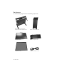
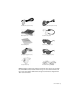
Box Contents The SD2620W shipping box contains the following components: Bottom monitor assembly with mirror support arms and mirror adjustment screws Bottom cable management cover Top monitor assembly Top cable management cover Beamsplitter assembly Two power cords (6-ft and 10-ft) iv | SD2620W
Two DVI cables (6-ft and 12-ft) Two Analog VGA cables (6-ft and 10-ft) Mirror-flip PCI card Short DVI cables (14-in) Product user’s guide Captain-style glasses (2 ea) Spring clip-style glasses (1 ea) Terminator-style glasses (2 ea) Soft, dry cloths (3 ea) Moistened cleaning pads (6 ea) NOTE: Both the Captain-style and the Terminator-style glasses, for use with the SD2620W monitor, feature the Planar logo on each side and white arm tips.
Contents Usage Notice ............................................................................................................. iii Box Contents............................................................................................................. iv Stereoscopic Viewing .............................................................................................. 1 StereoMirror™ Technology ..................................................................................... 2 Getting Started ....
Stereoscopic Viewing We live in a three-dimensional world. The human visual system can process the slightly different views of the world and translate the views into the perception of depth. This process is called stereopsis. In the last two centuries much effort has been devoted to the reproduction of depth perception, primarily with photography and more recently with computer graphic images.
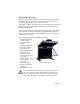
StereoMirror™ Technology A StereoMirror™ monitor consists of two AMLCD (Active Matrix Liquid Crystal Display) units, oriented at a 110º angle and mounted on a specially designed stand. A passive beamsplitter mirror bisects the angle formed between the two monitors, and there is a fine mechanical adjustment for the mirror angle between the two displays. One side of the glass mirror has a reflective coating, and the other side has an anti-reflective coating to minimize secondary reflections.
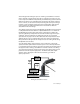
A block diagram describing the process of driving a StereoMirror™ monitor with a computer is shown below. The left eye and right eye images are sent to their respective AMLCDs independently and without any special treatment (with the exception of accommodating for the fact that the upper monitor is seen in a mirror; see discussion below). Presenting the stereo pair of images requires a setup or software application that accommodates dual-monitor stereo viewing.
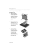
Getting Started Read all instructions before assembling the monitor. Improper assembly can result in damage to the display components. Assemble the unit 1. Remove the bottom monitor assembly from the shipping box and place it on a sturdy table or desktop. To keep the display surface clean, avoid touching the screen. 2. Remove the top monitor assembly from the shipping box. Loosen the two screws on the cover of the cable management compartment and remove the cover. 3.
4. Thread the cables from the top monitor through the rectangular hole in the cross bracket. 5. Replace the top and bottom cable covers, if desired. 6. Remove the beamsplitter from the shipping case. With the StereoMirror™ logo oriented to the lower right, insert the pins located on either side of the mirror frame into the corresponding slots on the mirror support arms. The pins should rest in the fully forward position of the mounting arm slots.
Select a graphics card The SD2620W unit requires a dual-output graphics card to drive the two monitors with a DVI signal. For professional applications that use OpenGL quad-buffered stereo, the graphics card should support OpenGL stereo as well. Typically, the two monitors should be in clone mode for these applications with stereo enabled. There are several compatible graphics card families. The NVIDIA Quadro FX line is recommended for OpenGL stereo applications.
Connect the cables The SD2620W unit comes with one 6-foot DVI cable, one 12-foot DVI cable, and one 14-inch DVI cable. 1. Plug one end of the 6-foot DVI cable into the primary port of the dual-channel DVI graphics card. Plug the other end into the bottom monitor of the SD2620W unit. 2. Plug one end of the 14-inch DVI cable into the secondary output of the dual-channel graphics card. Plug the other end into the input port (labeled “IN”) of the mirror-flip PCI card. 3.
Connect the power cords Two power cords are shipped with the unit. Use only the power cords supplied with the unit. 1. Plug the 10-foot cord into the AC power jack of the top monitor. Plug the 6-foot cord into the bottom monitor. Then plug the power connectors into a grounded outlet. 2. Turn on the power toggle switch on the back and the soft power switch on the front bezel of each of the two LCD monitors. 3. Power up the computer.
Product Use Operating in 2D mode Your SD2620W unit can operate either as a 3D stereoscopic monitor or in the standard 2D mode. Converting to 2D viewing can be accomplished by either turning off the power to one of the monitors or by putting the mirror into the locked upright position. To move the mirror to the raised position, use two hands to slide it up the mirror support arms and then raise it until it drops into the locked position.
The Source button allows you to select VGA or DVI input. The Menu button activates the OSD (on-screen display) main menu. Use the Exit button to close the OSD menu; this is also a DV mode hot key. The Auto button is a hot key for auto adjusting the display. A four direction (4D+1) button allows you to move up, down, left, and right within the menu systems. Press the four direction button to enter or exit menus.
Adjusting the Monitor's Display The monitor has four function control buttons by which you can select among functions shown on the OSD menu. The menu has been designed for easy user-viewing environments. OSD function menu To activate the OSD main menu, press the Menu button. The menu diagram pops up on the screen as shown. Use the 4D+1 key to navigate to the function you want to adjust. Push the 4D+1 key to enter a submenu and adjust the value. Push the 4D+1 key again to exit the submenu.
Function description Tables on the following pages describe all the functions on the OSD menus. MENU FUNCTION FUNCTION DESCRIPTION DV MODE This DV mode display setting can be selected by OSD (STANDARD/TEXT/sRGB/ MOVIE/GAMING/PHOTO) Default setting: TEXT BRIGHTNESS Adjust the brightness. Factory setting: 100.0% CONTRAST Adjust the image contrast. Factory setting:50.0% SHARPNESS Adjust the sharpness.
MENU FUNCTION FUNCTION DESCRIPTION EXPANSION MODE This function allows you to choose from different display modes: • Full: Expands all resolution to full screen. • Aspect: Enlarges native resolution to either horizontal or vertical limit. • Real: Displays native resolution. • Default setting: FULL. LEFT/RIGHT (Analog Input only) Adjust the horizontal image position. DOWN/UP (Analog Input only) Adjust the vertical image position.
MENU FUNCTION FUNCTION DESCRIPTION COLOR Choose different color TEMPERATURE temperature (9300K, 7500K, sRGB, USER). Default is USER. USER mode adjustable. Adjust the contrast and brightness of each color of the white balance. RED GREEN Allows you to adjust the Red/Green/Blue color gain. BLUE GAIN RED GREEN Allows you to adjust the Red/Green/Blue color offset. BLUE OFFSET SATURATION Adjust color depth: Increasing this value makes pictures more colorful; decreasing makes pictures less colorful.
MENU FUNCTION FUNCTION DESCRIPTION DDC/CI DDC/CI allows you to control certain settings of the monitor via computer. Default is ON. SIDE COLOR When Full is not selected in the Expansion Mode and the resolution is under the LCD panel native resolution, the picture does not display at full screen. The borders/sides around the picture can be customized. Adjust Side Color to customize the color of the border/sides around the picture.
MENU FUNCTION FUNCTION DESCRIPTION INFORMATION Provide information about resolution, H/V frequencies, and polarity of the input signal. INPUT SELECT This OSD reports the current signal being displayed. This OSD will automatically turn off after 2 seconds; you can also press the Exit key to close it. OSD WARNING This OSD gives a warning when the selected input signal is not NO SIGNAL active. After power on or when the input signal becomes inactive, this warning appears. No signal OSD is shown after 0.
MENU FUNCTION FUNCTION DESCRIPTION OSD WARNING This function gives warning for an input resolution or refresh OUT OF RANGE rate that the monitor cannot display. If video signal is not at the proper timing when the monitor powers on or when the input signal is changed, this message opens. It disappears after 45 seconds, or when you press the Exit key.
OSD Lock Out Function OSD Lock Function allows you to lock out the OSD menu and the button keys. To activate the OSD lock function, the monitor must be in a normal display mode with the information menu activated. Then follow the instructions below. Option 1: OSD lock – All buttons except the Power button are locked. Press Exit key + Menu key + Soft power key at same time. The monitor shows an “OSD Lock Out” message.
Monitor Specifications Displays Size 26” diagonal (583 mm) Display type Active matrix color TFT LCD panel Resolution 1920 x 1200 (WUXGA) Display dot 1920 x (RGB) x 1200 Display area (mm) 550.08 x 343.8 (H x V) Pixel pitch 0.
Plug and Play The unit supports the VESA DDC2B functions of Plug and Play. Environment Operating conditions, Temperature 5°C - 40°C (41°F – 104°F) Operating conditions, Relative humidity 20 to 80% (non-condensing) Storage conditions, Temperature -20°C to 60°C (-4°F to 140°F) Storage conditions, Relative humidity 5 to 85% (non-condensing) Size and weight System width 23.5" (596 mm) System depth 24.7" (628 mm) System height 29.
System Care Monitors. Turn off the monitors before cleaning. Use a dry, soft cloth, clean room wiper, or compressed air when cleaning the LCD panel surface. A soft cloth moistened with water and/or mild detergent can be used to clean the display housing and stand. Do not touch the LCD panel surfaces with sharp or hard objects. Do not use abrasive cleaners, waxes, or solvents for cleaning. Mirror. Use a dry, soft cloth, clean room wiper, or compressed air when cleaning the mirror surface.
Troubleshooting Problem Possible Solution No image appears on the screen. • Check that all the power cord connections are secure. • Check that the power buttons on the side and front of both monitors are switched on and that the power indicator light is green. • Check that the DVI cables are securely fastened to the graphics card, the mirror-flip PCI card, and the two monitors. • Make sure that the pins of the DVI connectors are not bent or broken. Partial image or incorrectly displayed image.
Warranty The SD2620W standard warranty includes a 1-year return to depot replacement warranty service. Return the defective part of the system for a replacement with a comparable product. • All components have a 30-day inspection warranty period • All system components have a 1-year warranty • Two business day delivery • Expedited Delivery Service available • Extended Warranty Terms are available Go to www.planar.
CRT Recycling If your new Planar monitor is replacing a CRT unit, keep the following in mind: • If the CRT unit is in good working condition, consider donating it to a school or nonprofit organization. It may qualify as a charitable tax deduction. • Do not throw away a CRT unit. Cathode Ray Tubes contain hazardous materials and cannot be discarded with other refuse. A number of recycling programs are available. Do an online search of “CRT Recycling” for potential service providers in your area.
For more information on StereoMirror™ technology, go to www.planar.com/advantages/whitepapers. Planar Customer Service Online Support For support available 24/7, visit our Online Technical Support page at www.planar.com/support. Online Technical Support is where you can find solutions for common problems, download documentation, view answers to frequently asked questions (FAQs), and get troubleshooting advice. Visit www.planar3d.com for specific questions about configuring the stereo monitor.
Planar Systems, Inc. 1195 NW Compton Drive Beaverton, OR 97006-1992 Customer Service E-mail: planarsupport@planar.com Online: www.planar.