LC1502R USER’S MANUAL www.planar.
Table of Contents Usage Notice Safety and Use Precautions . . . . . . . . . . . . . . . . . . . . . . . . . . . . . . . . . . . . . . . . . 3 Introduction About the LC1502R . . . . . . . . . . . . . . . . . . . . . . . . . . . . . . . . . . . . . . . . . . . . . . . . . 4 Package Overview . . . . . . . . . . . . . . . . . . . . . . . . . . . . . . . . . . . . . . . . . . . . . . . . . . 5 Installation Product Overview . . . . . . . . . . . . . . . . . . . . . . . . . . . . . . . . . . . . . . . . . . . .
Usage Notice Warning - To prevent the risk of fire or shock hazards, do not directly expose this product to rain or moisture. Warning - Please do not open or disassemble the product as this may cause electric shock. Safety and Use Precautions Follow all warnings, precautions and maintenance as recommended in this User's Manual to maximize the life of your monitor. • Turn off the product before cleaning. • Use only a dry soft cloth or clean room wiper when cleaning the LCD panel surface.
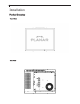
Introduction About the LC1502R The LC1502R is a high performance monitor designed for demanding applications. The monitor consists of a 15" diagonal flat panel liquid crystal display (LCD) housed in a metal enclosure with an integrated ambient light sensor to facilitate automatic brightness control.
Package Overview VGA Signal Cable Quick Start Guide
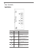
Installation Product Overview • Front View • Rear View
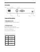
Connector View Connector Descriptions 1. Video Interface Connector Standard D-sub Analog; 15-pin D-sub connector 2. Power Input Connector Connector type: 4-pin mini DIN socket Manufacturer: Singatron Enterprise Co.
3. External Dimming Connector Connector type: Molex Micro Fit 3.
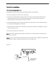
Start Your Installation Connecting the Display (Figure 1.0) To configure the monitor, please refer to the following figure and procedures. 1. Be sure the computer or video source is turned off. 2. Connect the 12V DC power(1.0). During initial turn on with no video applied, the display will automatically power on with a self test pattern displayed. The self test pattern consists of alternating screens of black, white, red, green, and blue. 3.
User Controls Control Buttons No./ Icon Control Function Menu button Displaysthe theOSD OSDmenus menus Display Select/Auto Select- To select the adjustment items from OSD menus. Auto- To activate the “Auto Adjustment” function to obtain an optimum image. Brightness Minus/ Minus 1.Decreases 1. Decreases the the brightness value of theofadjustment items. the display image. 2. Decreasesvalue the minimum 2.Decreases of the brightness limit of the items. display image.
How to Use the OSD Menus 1. Press the "Menu" button to pop up the on-screen menu and to select between the four main menus. 2. Choose the adjustment items by pressing the "Select/Auto" button. 3. Adjust the value of the adjustment items by pressing the "+" or "-" button. 4. The OSD menu will automatically close if you have left it idle for a pre-set time.
Second OSD Menu: Display Mode OSD Off-Time Language Text-Graphic Reset • Display Mode The display mode shows the display resolution, horizontal scan frequency, and vertical refresh of the current mode. • OSD Off-Time Adjusts the time period for OSD menu to disappear. • Language Allows menu language selection from among English (default), German, Italian, French, Spanish, and Japanese • Text-Graphic Toggles between VGA text mode (mode M03H) and graphic mode (mode M13H).
Brightness Control The brightness of the monitor may be controlled automatically or manually, and the minimum brightness is adjustable. By default, the monitor is configured for automatic brightness control with a minimum brightness setting of approximately 250 cd/m2. Automatic Brightness Control In automatic brightness control mode, a photo sensor mounted on the front of the display measures the ambient lighting condition (the illuminance).
Manual Brightness Control In manual brightness control mode, an externally supplied voltage determines the monitor brightness. To use manual brightness control mode instead of the default automatic brightness control mode: 1. set pin 4 (/EXT_DIM) of the external dimming connector (J1) to a logic low 2. apply a 0 to 5V analog input to pin 3 (DIM_INPUT) of the external dimming connector A potentiometer may be used to apply the voltage to the DIM_INPUT, as shown in the figure below.
Minimum Brightness Limit The factory set minimum brightness is approximately 250 cd/m2. In most applications the factory setting is desired to maintain the widest dimming range possible. But for applications where 250 cd/m2 is too low but some dimming is still desired, the minimum brightness limit may be increased. The OSD controls are used to access and change the minimum brightness limit setting, as described in the User Controls section of this manual.
As with any OSD setting, a change to the minimum brightness limit will be permanently stored and will be unaffected by turning off the monitor power. The minimum brightness limit will affect the minimum brightness of both the automatic brightness control mode and the manual brightness control mode identically. Below is a graph showing the impact of various minimum brightness limit settings on the automatic brightness control mode.
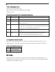
Specifications Electrical and Optical Parameter Min Typ Max Units Input Power, Voltage 11.4 12.0 12.6 volts Input Power, Current 3.95 4.3 amps Monitor Power Consumption 47.4 49.2 watts Conditions/Notes Logic High 4.0 5 5.4 volts For logic inputs Logic Low -0.4 0 1.
Mechanical and Environmental Parameter Specification Operating Temperature 0 to 50°C Operating Humidity 30 to 85% RH, non-condensing Storage Temperature -20 to 60°C Storage Humidity 10 to 85% RH, non-condensing Active Area Surface Treatment Anti-glare, 3H hard coating Weight < 3 kg Mechanical Shock Half sine wave, 30g, 11ms, 3 shocks per axis Sine sweep vibration, operating 10~500 Hz, 0.25g o-p, 0.25 oct / min Random sweep vibration, operating 10~500 Hz, 0.
Reliability and Life Parameter Specification Mean Time Between Failures 20k hours at 25°C, 90% confidence level Time to 50% brightness decay from initial brightness 40k hours minimum at 25°C, operating continuously at maximum brightness Safety and Regulatory Certifications A. FCC Certification FCC Part 15, Subpart B, Class B - Conducted and Radiated Tests B.
Available Options Power Supply and AC Power Cord The LC1502R requires a 12VDC power input. Many users will have the required 12VDC available in their existing system. Alternatively, a power supply that is appropriately rated for the LC1502R is available from Planar. The supply is available with the AC power cord configured with either a European plug or a US plug.
Cooling Kit For outdoor applications, a cooling kit may be desired to prevent excessive heating of the LCD display. In direct sunlight, the front surface of the display (the LCD cell) may reach temperatures well above the ambient temperature.
Touch Screens The LC1502R is available with two different types of touch screen technology: near field imaging (NFI) and capacitive. Both come pre-installed; the touch screen itself is mounted to the front of the monitor and the touch screen controller module is mounted on the back. NFI technology utilizes a thick glass substrate that provides “vandal-proof” protection. Capacitive technology is more rugged than resistive, and is usually the touch screen of choice for heavy use, unattended environments.
Set up 1. Refer to Planar mechanical outline drawing 076-0596-xx for the recommended mounting pattern for this display. 2. Separate the LCD monitor from the touch bezel for mounting. a. Remove the controller cover in order to remove the touch screen controller cable. b. Unscrew the 2 M4 nuts on the side mounting brackets. c. Separate the LCD monitor 3. Mount the touch screen to the inside surface of your device. 4. Install the monitor on the hooks and reconnect the flex cable to the controller. 5.
Capacitive Touch Screen LC1502R with Capacitive Touch Screen The LC1502R with capacitive touch screen – model LC1502RTC – is designed to be installed in enclosures placed in high ambient lighting environments that are protected from extreme environmental conditions. It utilizes a standard 3M capacitive touch screen. Set Up 1. Refer to Planar mechanical outline drawing 076-0587-xx for the mounting hole locations. 2.
Appendix Troubleshooting If you are experiencing trouble with the LCD display, refer to the following. If the problem persists, please contact your local stat or visit Planar Support at www.Planar.com/support. See support contact information on rear cover. For all video image problems, first try using the Auto-Adjustment in the OSD menu. Problem: No image appears on screen.
Going to Sleep This message means the LCD display is under the power saving mode. In addition, the LCD display will go to this sleeping mode when experiencing a sudden signal disconnecting problem. Unsupport Mode This message means the signal of the computer graphic card is not compatible with the LCD display. When the signal is not included in the compatibility mode we have listed in the Appendices of this manual, the LCD display will appear this message.
Description of Warranty Seller warrants that the Goods will conform to published specifications and be free from defects in material for 12 months from delivery. To the extent that Goods incorporate third-party-owned software, Seller shall pass on Seller's licensor's warranty to Buyer subject to the terms and conditions of Seller's license. Warranty repairs shall be warranted for the remainder of the original warranty period.
Planar Systems, Inc. Customer Service 24x7 Online Technical Support: http://www.planar.com/support Americas Support Tel: 1-866-PLANAR1 (866-752-6271) Hours: M-F, 7:30am - 5pm Pacific Time Europe and Asia-Pacific Support Tel: +358-9-420-01 Hours: M-F, 7:00am - 4pm CET © 2004 Planar Systems, Inc. 09/04 Planar is a registered trademark of Planar Systems, Inc. Other brands and names are the property of their respective owners. Technical information in this document is subject to change without notice.