Model #: ___________________________ Serial #: ___________________________ Date Purchased: ____________________ Installation & Operation Manual Model SRTG Floor Model Gas Rethermalizer Built after 8/2005 C E E S I G N D D CERT I F I ED E R T I F I L20-291, rev.
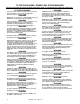
TO THE PURCHASER, OWNER AND STORE MANAGER Please review these warnings prior to posting them in a prominent location for reference. TO THE PURCHASER Post in a prominent location the instructions to be followed in the event that an operator smells gas. Obtain this information from your local gas supplier. WARNING DO NOT store or use gasoline or other flammable vapors and liquids in the vicinity of this or any other appliance.
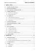
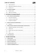
SRTG: Gas Floor Model Rethermalizer TABLE OF CONTENTS 1. INSTALLATION......................................................................................1 1.1. CHECKING YOUR NEW APPLIANCE.......................................................................................... 1 1.2. INSTALLATION CLEARANCES ................................................................................................... 2 1.3. LEG/CASTER INSTALLATION AND LEVELING ..................................................
TABLE OF CONTENTS 2.3.3. TIMER OPERATION ............................................................................................................. 17 2.3.4. ADDITIONAL CONTROLLER FUNCTIONS ......................................................................... 18 2.3.5. COOKING TIPS..................................................................................................................... 18 2.4. APPLIANCE SHUTDOWN........................................................................
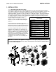
INSTALLATION SRTG: Gas Floor Model Rethermalizer 1. INSTALLATION 1.1. CHECKING YOUR NEW APPLIANCE Your new Pitco appliance has been carefully packed into one crate. Every effort has been made to ensure that it is delivered to you in perfect condition. As you unpack your new appliance, inspect each of the pieces for damage. If something is damaged, DO NOT sign the bill of lading. Contact the shipper immediately; the shipper is only responsible for 15 days after delivery.
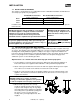
INSTALLATION 1.2. INSTALLATION CLEARANCES The clearances shown below are for combustible and non-combustible installations and will allow for safe and proper operation of your appliance. Back Sides Floor Combustible Construction Inches (centimeters) 6.0" (15.24cm) 6.0" (15.24cm) 6.0" (15.24cm) Non Combustible Construction Inches (centimeters) 0.0" (0.0cm) 0.0" (0.0cm) 6.0" (15.24cm) In addition to the above clearances there must also be at least 16 inches (40.64cm) of aisle space in front of the unit.
INSTALLATION SRTG: Gas Floor Model Rethermalizer 1.4. PLUMBING CONNECTIONS The plumbing installation should be done by a licensed plumber and must comply with local and national codes. 1.4.1. WATER INLET CONNECTIONS If a faucet or water fill option is equipped on your appliance connections to a potable water supply will be required. If a single water connection is required it is recommended that the appliance is connected to hot water supply.
INSTALLATION 1.5. GAS CONNECTION Your appliance will give you peak performance when the gas supply line is of sufficient size to provide the correct gas flow. The gas line must be installed to meet the local building codes or National Fuel Gas Code ANS Z223.1 and NFPA 54 (latest editions). In Canada, install the appliance in accordance with CSA B149.1 or .2 and local codes.
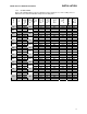
INSTALLATION SRTG: Gas Floor Model Rethermalizer CH CY CZ DE DK EE ES FI FR GB GR HU 16 16 16 16 16 16 16 16 16 16 16 16 16 #42 N22 YES #53 LP16 YES #42/2.58 mm N22 NO #53 LP16 YES #42 N22 YES #53 LP16 YES #42 N22 YES #53 LP16 YES N/A N/A N/A #53 LP16 YES #42 N22 YES #53 LP16 YES #42/2.58 mm N22/MF28 YES #53 LP16 YES #42 N22 YES N/A N/A N/A #42 N22 YES N/A N/A N/A #42 N22 YES #53 LP16 YES #42 N22 YES N/A N/A N/A #42/2.
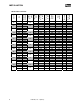
INSTALLATION LU LV MT NL NO PL PT RO SE SI TR 6 16 16 16 16 16 16 16 16 16 16 16 16 16 16 L20-291, rev. 1 (05/11) #42 N22 YES #53 LP16 YES #42 N22 YES N/A N/A N/A #42 N22 YES #53 LP16 YES #42 N22 YES N/A N/A N/A #42 N22 YES #53 LP16 YES #42 N22 YES N/A N/A N/A N/A N/A N/A #53 LP16 YES 2.
SRTG: Gas Floor Model Rethermalizer INSTALLATION 1.6. ELECTRICAL CONNECTIONS It is advised that this power supply be plugged into a wall receptacle that is controlled by the ventilation control. This will prevent the appliance from being operated without the ventilator on. If your appliance requires an electrical connection, the power requirements are listed below. Input Voltage Current per unit North America International 120 VAC, 50/60 Hz 220, 230 or 240 VAC 50/60 Hz 1.0 Amp 0.
INSTALLATION WARNING If your appliance is uses line current, it is equipped with an oil proof, electrical supply cord with a three-prong safety plug. This is to protect operators from electrical shock hazard in the event of an equipment malfunction. DO NOT cut or remove the grounding (third) prong from this plug; it should be plugged into a properly grounded three-prong receptacle. 1.7. VENTILATION AND FIRE SAFETY SYSTEMS Your new appliance must have proper ventilation to function safely and properly.
SRTG: Gas Floor Model Rethermalizer INSTALLATION 1.8. INSPECTION Before you begin filling and adjusting the appliance, perform the following visual checks: After the appliance is in its permanent location, check the levelness. Any additional leveling that is necessary can be performed as previously described. Ensure that the probe, and high temperature limit is in place and secure. Check the high limit bulb mounting screws to ensure that they are tight.
INSTALLATION 1.9. INITIAL ADJUSTMENTS After your appliance has been properly installed as described in the installation section of this manual, it will need to be adjusted to ensure that it will perform as designed. A qualified person must perform these adjustments. To perform these adjustments the following tools will be needed: • Manometer • Digital Thermometer (Temperature Probe) • DC Microammeter 1.9.1. FILLING THE APPLIANCE Refer to the following procedure to fill the cook tank prior to operation. 1.
INSTALLATION SRTG: Gas Floor Model Rethermalizer 1.9.3. PILOT FLAME ADJUSTMENT Perform this procedure with the pilot lit. Note: This procedure requires the use of a DC microammeter. 1. Connect the DC microammeter between the flame sensor terminal and the flame sensor lead. Observe proper polarity: if the meter needle goes below 0, reverse the leads. The current reading must be 1.0 A or greater, (0.15 A or greater for CE units). 2.
INSTALLATION 1.9.4. MAIN BURNER SYSTEM ADJUSTMENT For the main burners to operate the gas supply valve must be open and the thermostat must be turned on. The main power switch must be on. The main burners receive gas from the main gas supply through the thermostatically controlled valve. When the water temperature drops below the preset temperature the gas control valve opens. The main burners must be adjusted to deliver optimum flame. Refer to the following procedure to adjust the main burners. 1.
SRTG: Gas Floor Model Rethermalizer INSTALLATION CAUTION Be careful not to disturb the probe and high temperature limit during operation and cleaning of this appliance. 1.10. INITIAL CLEANING When your appliance is shipped, many of its parts are covered with a thin coat of oil for protection. Before the appliance is ready for cooking it must be cleaned. This will remove the oil coating and any foreign matter that may have accumulated during storage and shipment.
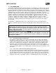
OPERATION 2. OPERATION An operator’s manual for your appliance’s specific control type should be included with this manual. Refer to that manual prior to operating this appliance. 2.1. OPERATIONAL FEATURES The diagram below outlines some of the key operational components of your appliance. Refer to the following sections of this manual to learn more about these features. 14 L20-291, rev.
SRTG: Gas Floor Model Rethermalizer OPERATION 1. Cook Tank 2. Controller (Not on all Models) Controls the water temperature inside the cook tank. Optional timers are located on the controller (if equipped). If the controller has an ON/OFF button, it will be used to turn ON the controller as well as other features on the appliance. 3. Door (Shown Open) Provides access to the drain valve handle, high temperature reset button and gas valve, pilot, burners and shutoff valves. 4.
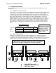
OPERATION 2.2. FILLING THE APPLIANCE 2.2.1. FILLING THE COOKER TANK It is recommended that the cooker tank is filled with hot water. This will greatly decrease the time it takes for the appliance to reach operating temperature. Refer to the following procedure to fill the cook tank prior to operation. CAUTION This appliance is not designed for cooking with oil. Fill with potable water only. Tank Capacity Model SRTG Capacity 17-1/2 Gal. (66.2 Liters) DRAIN VALVE CLOSED 1.
OPERATION SRTG: Gas Floor Model Rethermalizer 2.3. APPLIANCE START UP Refer to the following procedure to start the appliance prior to operation. 1. Ensure that the drain valve is closed. 2. Fill the cook tank with water. (See section 2.1 “Filling the Appliance”) 3. Light the appliance. (See section 1.8.2 “Lighting Instructions”) 4. Turn the I/0 (ON/OFF) switch, to the I (ON) position. WARNING NEVER operate the appliance with an empty cook tank. It may void the warranty.
OPERATION 2.4.4. ADDITIONAL CONTROLLER FUNCTIONS Some controllers have additional functions not described in this manual. If your appliance’s controller has additional functions, refer to the controller’s operation manual to access these functions. 2.4.5. COOKING TIPS Always follow the food manufacturer’s directions and only use vacuum-sealed products in this appliance. Some products can be reheated and held at the same temperature.
SRTG: Gas Floor Model Rethermalizer PREVENTATIVE MAINTENANCE 3. PREVENTATIVE MAINTENANCE 3.1. DAILY PREVENTATIVE MAINTENANCE Performing the preventative maintenance steps below on a daily basis will keep your equipment safe and at peak performance. During the cooking process, starch build up will form on the temperature probes, tank and heating element. It may be necessary to clean these components more then once a day.
PREVENTATIVE MAINTENANCE 3.2.1. DELIMING 1. Read the “operation” section of this manual prior to filling or operating the appliance. 2. Following the manufacturer’s deliming instructions, remove deposits from the tank’s interior. 3. When cleaning is complete, rinse the inside of the tank and its components thoroughly with cool water. Continue to rinse at least twice or until the cleaner has been completely and thoroughly rinsed from the tank. 4. Using a clean dry cloth, wipe out all of the water. 3.3.
SRTG: Gas Floor Model Rethermalizer PREVENTATIVE MAINTENANCE Check ignition system and adjust pilot flame as required. Check flame sensor reading. Matchless Ignition: Check gap spacing and clean igniter. Recheck for gas leaks after inspection. 3.4. VENTILATION HOOD Proper ventilation hood operation is very important for the correct operation of this appliance and the safety of personnel.
TROUBLESHOOTING 4. TROUBLESHOOTING 4.1. POWER FAILURE If electric power is removed for any reason, the appliance will shut down. Wait five minutes after the power is restored before attempting to restart the appliance. This will allow time for any gas that may have accumulated in the burner or tubes to dissipate. To restart the appliance, follow the appliance start up procedure in section 2.2. CAUTION DO NOT attempt to operate this appliance during a power outage. 4.2.
TROUBLESHOOTING SRTG: Gas Floor Model Rethermalizer 4.4. TROUBLESHOOTING CHART Problem Probable Causes No power to appliance. Circuit Breaker tripped. Corrective Actions Check main building power supply. Reset circuit breaker. Controller does not Flip I/0 switch to I position and turn on I/0 Switch in 0 position. activate. controller. Controller not turned on. Turn on controller. Power Cord loose or not connected. Connect power cord. Turn on water. Autofill does not add Water not turned on. water.
In the event of problems with or questions about your order, please contact the Pitco Frialator factory at: (603) 225-6684 World Wide Website Address: www.pitco.com In the event of problems with or questions about your equipment, please contact the Pitco Frialator Authorized Service and Parts representative (ASAP) covering your area, or contact Pitco at the numbers listed to the left. MAILING ADDRESS – P.O. BOX 501, CONCORD, NH 03302-0501 SHIPPING ADDRESS – 10 FERRY ST., CONCORD, NH 03301 L20-291, rev.