IMPORTANT FOR FUTURE REFERENCE Please complete this information and retain these instructions for the life of the equipment: Serial #: __________________________ Date Upgraded: ___________________ Technician: _________________________ Installation Instructions for the PITCO Self-Cleaning Burner System L80-029 Rev 5 10/07 ENGLISH Model #: __________________________
RETAIN THESE INSTRUCTIONS FOR FUTURE REFERENCE WARNING The power supply to the appliance MUST be disconnected before performing this procedure. WARNING Ensure that the gas supply to this appliance is turned off before performing this procedure. WARNING Use only parts supplied with this kit. Use of any parts other than those supplied with this kit will void the warranty and could cause unsafe conditions or improper operation of your appliance.
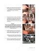
Theory of Operation: A natural gas burning appliance requires roughly 10 cubic feet of air to properly combust a single cubic foot of gas. Minute airborne particles entrained during this process pass through the combustion system and are incinerated. However, some particles may be trapped within the combustion system, building up over time, causing an eventual decrease in the operational efficiency of your appliance.
Follow this procedure for Installation of Self Cleaning burners and SCBS arm: a. Disconnect the control harness from the main gas valve and tuck it out the way to avoid damaging the harness during this procedure. b. If your appliance has a solid-state control (or auxiliary thermostat) behind the door, remove it at this time.
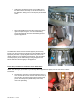
e. Using a 1 1/16” wrench and a 7/8” wrench, loosen the brass fitting on the top of the gas valve and disconnect the gas valve from the manifold inlet. This will allow you to drop the gas valve down and keep it out of the way during burner replacement. f. Using a 5/16” wrench, nut driver or screw gun bit, remove all burners by removing the (2 ea.) self threading screws holding them into the burner rack. Retain these for reinstallation of the new burners.
i. Capture the remaining burners on the SCBS Arm in the same manner as in step h, and secure them into the appliance, taking care not to strip the pre-threaded holes. j. Secure the SCBS Arm to left side of the burner to the right of the pilot using two 10 X 24 self-threading screws provided with the Pitco Self-Cleaning Burner System Upgrade Kit. The SCBS Arm should now be mounted properly and securely. Inspect your work to insure that the burners are installed correctly.
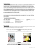
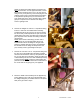
NOTE: CE approved models will have a pressure test fitting in this location. For CE approved models, remove this pressure test fitting using a 7/16” (12 mm) wrench. Using a 3/16” (5 mm) hex key, remove the plug from the auxiliary pressure tap on the manifold inlet and replace it with pressure tap fitting that you removed from the TOP (Outlet side) of the valve. Use teflon tape or apply pipe joint compound on the threads of the fitting to ensure a gas-tight seal. b.
e. Thread the compression nut on the corrugated tubing end of the SCBS Valve Assembly onto the orifice assembly that you inserted into the runner tube in step c and tighten with a 1/2” (13 mm) wrench. f. Install the orifice retainer bracket onto the pilot bracket and SCBS Orifice assembly. This will secure the orifice assembly into the runner tube. g. Tighten ALL joints on the SCBS Valve assembly with a ½” (13 mm) wrench. Reinstall the pilot tubing into the gas valve. h.
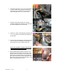
b. Disconnect the wiring harness from the relay board mounted behind the front panel and remove the relay board and insulation paper. Be sure to retain the screws. The existing relay board may or may not have a jumper plug as shown. If it does, remove it from the old relay board and install it into the same position on the “new” SCBS relay board provided. c.
e. If the appliance you are upgrading does NOT have a Solid State Control, proceed to step f in this section. If the appliance that you are upgrading has a Solid State Control, feed the other ends of the SCBS Harness through the unused portion of the strain relief holding the Solid State Control Harness and proceed directly to step h in this section. NOTE: If needed, you can carefully nudge open the area in the strain relief with a screwdriver to make additional room to insert the SCBS harness.
i. Connect the SCBS Harness to the SCBS Valve as shown. The red and violet wires must be connected to the vertically oriented tabs on the valve and the green (ground) wire must be connected to the bottom, horizontally oriented tab on the valve. The grey wires will be connected to the Thermal Limit at a later point in the upgrade process. j. Route the SCBS Harness along the main control harness and wire tie it to the control harness.
Follow this procedure to check proper operation of the Pitco Self-Cleaning Burner System: WARNING Ensure that tank is filled to the level line with oil before turning the appliance on. Turning the appliance on with an empty or partially filled tank could cause an unsafe condition, which could lead to damage to the appliance, property damage or personal injury. a. Reconnect the power supply and turn on the gas supply to the appliance. b.
appliance is in operation, or can be detected visually by watching the burner flame through the air collars. The sound of the burners will be inconsistent and the flame may appear to ‘peel’ off of the burner face. A certain amount of flame roll out during ignition is normal. However, excessive flame roll out during burner operation is abnormal. Excessive flame roll out will cause undue heating in the burner area and will cause the thermal cut out switch to trip.
TROUBLESHOOTING Should there be a problem with your appliance, use the following tables to isolate possible faults before calling Pitco Technical Support. POSSIBLE CAUSES PROBLEM Appliance will not run, front panel lights are not ON. Appliance will not run, front panel lights are ON. A. B. C. D. E. F. A. B. C. Main breaker in OFF position. Gas supply turned OFF. Appliance unplugged. Blown control fuse. Faulty transformer. Defective controller.
13 L80-029 Rev 5 10/07
L80-029 Rev 5 10/07 14
15 L80-029 Rev 5 10/07
L80-029 Rev 5 10/07 16
17 L80-029 Rev 5 10/07
L80-029 Rev 5 10/07 18
19 L80-029 Rev 5 10/07
L80-029 Rev 5 10/07 20
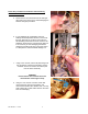
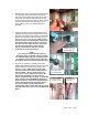
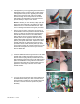
Before and After: Visual Aid The below images show a typical model SG14 burner assembly before and after the installation of the SCBS upgrade. Wire harnesses and pilot tubing are omitted to provide better clarity. In order to give the installer a sense of part orientation and location, the gas piping parts (valve, tubing, runner arm and fittings) of the SCBS system are shaded. For clarity, the thermal limit switch assembly is not shaded.
In the event of problems with or questions about your order, please contact the Pitco Frialator factory at: (800) 258-3708 US and Canada only or (603) 225-6684 World Wide In the event of problems with or questions about your equipment, please contact the Pitco Frialator Authorized Service and Parts representative (ASAP) covering your area, or contact Pitco at the numbers listed to the left. MAILING ADDRESS – P.O. BOX 501, CONCORD, NH 03302-0501 SHIPPING ADDRESS – 10 FERRY ST.