IMPORTANT FOR FUTURE REFERENCE Please complete this information and retain these instructions for the life of the equipment: Model #: __________________________ Serial #: __________________________ Date Upgraded: ____________________ Technician: ________________________ Installation Instructions for the PE14D/PG14D Manual Fill Option L80-045 Rev 0 (11/07)
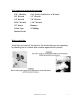
Tool required to perform this upgrade: 5/32” Allen Key 5/16” Socket, Nut Driver, or Wrench 3/8” Wrench 1/2” Wrench 3/4” Wrench 7/8” Wrench 13/16” Wrench 1 1/4” Wrench 1/2” Punch Hammer Teflon Tape #2 Phillips Channel Locks Before you begin : Verify that you have all the parts for the model that you are upgrading by checking the kit number and contents against the kit picture.
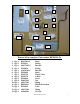
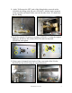
1 2 3 4 5 6 7 8 9 10 11 12 14 13 Ensure kit is complete. Part number B8702901-CL. 1. Qty.1 2. Qty.3 3. Qty.1 4. Qty.1 5. Qty.1 6. Qty.1 7. Qty.1 8. Qty.2 9. Qty.2 9. Qty.4 10. Qty.1 11. Qty.1 12. Qty.1 13. Qty.1 14. Qty.
15. Qty.
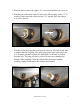
1. From the back, remove the eight 5/16” screws that hold the rear cover on. 2. With the rear of the tank exposed, remove the fill port plug with a 1/2” in wrench. Then remove the reducer with a 7/8” wrench. Save the reducer, as it will be reused. 3. With the nylon plug exposed it can now be removed. The hole in the tank is smaller than the coupling. The nylon plug needs to be removed out the rear. It can be punched out from the front inside of the tank, or pulled from the rear.
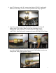
4. Apply Teflon tape to the 90° compression fitting (PP10911) and install. Make sure the fitting is at the 3 o’clock position when fully tightened. 5. Apply the compression fitting (PP10830) to the front end of the fill piping (A8017501) before install. Apply the remaining two 90° compression fitting (PP10911) to each end of the supply piping (A8017401). After each end is compressed remove the body of the fitting 6. Install the fill piping from the rear of the unit.
. Apply Teflon tape to the rear fitting of the supply piping. Install the check valve (PP10726) onto the rear fitting of the supply piping with the support bracket (A1826101-C) between the valve and fitting. 8. Install the supply piping assembly from the front. The assembly should contain the piping, two fittings, check valve, and mounting bracket. Mount the bracket to the bottom rear cabinet brace using the two Phillips head screws (PP10694) and two of the six kep nuts (P0092300).
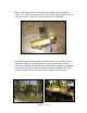
9. From the front of the unit, remove the four Allen head screws with a 5/32” Allen Key. Unplug the computer and set front panel assembly aside. Remove the heat shield via three 5/16” screws. 10. With the heat shield removed remove the no fill option cover plate. The plate is held in place with three 5/16” screws with 3/8” kep nuts. 11. With the cover removed you should see your supply and fill piping.
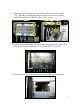
11. Apply Teflon tape the NPT ends of the fitting bodies removed earlier. Assemble the fittings with fill valve (PP10945). Add the knob extension to the assembly and install. Make sure the flat side of the “D” shaft faces the 90° fitting. 12. Install the manual fill option cover plate (A1826101-C) using the original hardware. Install two the u-bolts (PP10270) and four kep nuts (P0092300) and tighten. 13. Using a pair of channel locks brake off the extra studs of the U-bolts.
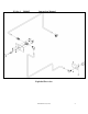
14. Apply the new manual fill option overlay (A6066901) to the new manual fill option bezel (B3615401-C). With a 3/8” wrench, remove the four kep nuts that hold the controller to the original bezel and install it onto the new bezel using the original hardware. 15. Reconnect the controller plug and mount the bezel using the original hardware. Install the fill knob and tighten the set screw. Make sure the knob only travels within the markings of the overlay. 16.
THIS PAGE LEFT INTENTIONALLY BLANK L80-045 Rev0 (11/07) 11
In the event of problems with or questions about your order, please contact the Pitco Frialator factory at (800)258-3708 US and Canada only (603)225-6684 World Wide In the event of problems with or questions about your equipment, please contact the Pitco Frialator Authorized Service and Parts representative (ASAP) covering your area, or contact Pitco at the numbers listed to the left. MAILING ADDRESS – P.O. BOX 501, CONCORD, NH 03302-0501 SHIPPING ADDRESS – 10 FERRY ST.