Model #: ___________________________ Serial #: ___________________________ Date Purchased: ____________________ Installation & Operation Manual Covering all Solstice & Solstice Supreme With Matchless Ignition Built after 08/2000 C E E S I G N D D CERT I F I ED E R T I F I L20-378 rev.
TO THE PURCHASER, OWNER AND STORE MANAGER Please review these warnings prior to posting them in a prominent location for reference. TO THE PURCHASER Post in a prominent location the instructions to be followed in the event that an operator smells gas. Obtain this information from your local gas supplier. WARNING DO NOT store or use gasoline or other flammable vapors and liquids in the vicinity of this or any other appliance. Do not spray aerosols in the vicinity of this appliance when it is in operation.
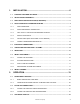
1. INSTALLATION ................................................................................... 6 1.1. CHECKING YOUR NEW APPLIANCE .......................................................................................... 6 1.2. INSTALLATION CLEARANCES ................................................................................................... 6 1.3. HEAT DEFLECTOR INSTALLATION (IF EQUIPPED) ................................................................. 6 1.4.
2.4. COOKING..................................................................................................................................... 23 2.4.1. TIMER OPERATION ............................................................................................................. 23 2.4.2. BASKET LIFT OPERATION.................................................................................................. 23 2.4.3. SPINFRESHTM........................................................................
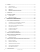
4. TROUBLESHOOTING ....................................................................... 31 4.1. POWER FAILURE........................................................................................................................ 31 4.2. HIGH TEMPERATURE LIMIT SWITCH....................................................................................... 31 4.3. DRAIN VALVE INTERLOCK & FLOAT SWITCH (NOT ON ALL MODELS) ............................. 31 4.4.
INSTALLATION 1. INSTALLATION 1.1. CHECKING YOUR NEW APPLIANCE Your new Pitco appliance has been carefully packed into one crate. Every effort has been made to ensure that it is delivered to you in perfect condition. As you unpack your new appliance, inspect each of the pieces for damage. If something is damaged, DO NOT sign the bill of lading. Contact the shipper immediately; the shipper is only responsible for 15 days after delivery.
INSTALLATION 1. Remove the two self-drilling screws from the top, back area of the appliance. 2. Position the heat deflector so that the angled portion of the deflector is facing toward the front of appliance. Secure the heat deflector to the back of the unit using the two previously removed fasteners. 3. When properly installed the angled section of the heat deflector will extend over the flue opening to redirect the heat. It SHOULD NOT cover the flue opening.
INSTALLATION 1.4.1. GAS CONNECTION Your gas appliance will give you peak performance when the gas supply line is of sufficient size to provide the correct gas pressure. The gas line must be installed to meet the local building codes or National Fuel Gas Code ANSI Z223.1 Latest Edition. In Canada, install the appliance in accordance with CAN/CGA-B149.1 or .2 and local codes. In Australia, install the appliance in accordance with AS/NZS 5601.
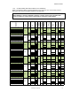
INSTALLATION 1.4.5. CE GAS TABLE (NOT APPLICABLE TO ALL MODELS) Refer to the following table for gas specifications for the country of use. If the country of use is NOT listed, refer to the information stamped on the data plate.
LU FR BE DE NL BG, CH, CY, CZ, FR, DE, GB, GR, HU, IE, IT, LU, MT, NL, PL, PT, RO, ES, SI, SK, TR AT, BG, CH, CZ, DK, EE, FI, GB, GR, HU, IE, IT, LT, LV, NO, PL, PT, RO, ES, SI, SK, SE, TR LU FR BE DE NL BG, CH, CY, CZ, FR, DE, GB, GR, HU, IE, IT, LU, MT, NL, PL, PT, RO, ES, SI, SK, TR AT, BG, CH, CZ, DK, EE, FI, GB, GR, HU, IE, IT, LT, LV, NO, PL, PT, RO, ES, SI, SK, SE, TR LU FR BE DE NL BG, CH, CY, CZ, FR, DE, GB, GR, HU, IE, IT, LU, MT, NL, PL, PT, RO, ES, SI, SK, TR AT, BG, CH, CZ, DK, EE, FI, GB, GR,
LU FR BE DE NL BG, CH, CY, CZ, FR, DE, GB, GR, HU, IE, IT, LU, MT, NL, PL, PT, RO, ES, SI, SK, TR AT, BG, CH, CZ, DK, EE, FI, GB, GR, HU, IE, IT, LT, LV, NO, PL, PT, RO, ES, SI, SK, SE, TR LU FR BE DE NL BG, CH, CY, CZ, FR, DE, GB, GR, HU, IE, IT, LU, MT, NL, PL, PT, RO, ES, SI, SK, TR AT, BG, CH, CZ, DK, EE, FI, GB, GR, HU, IE, IT, LT, LV, NO, PL, PT, RO, ES, SI, SK, SE, TR LU FR BE DE NL BG, CH, CY, CZ, FR, DE, GB, GR, HU, IE, IT, LU, MT, NL, PL, PT, RO, ES, SI, SK, TR AT, BG, CH, CZ, DK, EE, FI, GB, GR,
LU FR BE DE NL BG, CH, CY, CZ, FR, DE, GB, GR, HU, IE, IT, LU, MT, NL, PL, PT, RO, ES, SI, SK, TR Nominal Gas Rate (m3/hr) Pilot Orifice (code) Burner Orifice Burner Pressure (mbar) Supply Pressure (mbar) Net Input (kW) Gross Input (kW) Appliance Category Gas YES 2.9 I 2H G20 G20/G25 G20/G25 G25 I 2E I 2ESI I 2E+ I 2ELL I 2L G31 I 3P Nat SSH75 LP 20 27.7 30.8 28.3 #45 10 N22 20/25 #45/#43 25 #45 50/37 25.4 1.35 mm NO YES YES LP16 2.9?3.4 3.4 YES 1.2 YES 3.
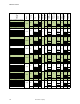
INSTALLATION SG14T SG18 SG6H MGII MGIIT SGH50 SGH50T SGM18D4 SGM18D5 SGM1824 SGM20 SGM24 SGM34 SSH55 SSH55T SSH55R SSH55TR SSH60 SSH60R SSH60W SSH60WR SSH75 SSH75R Nat #41 4.0 LP #53 10.0 Nat #38 4.0 LP .062" 10.0 Nat #43 4.0 LP 1.45 mm 10.0 Burner Pressure Orifice Tip Size 75kBtu (22kW) SGC 110kBtu (33kw) SG14 122kBtu (36kW) SG14R 100kBtu (30kW) SG14T 140kBtu (40kW) SG18 140kBtu (40kW) SG6H NOT APPROVED FOR USE IN THIS COUNTRY 80kBtu (23.
INSTALLATION 1.5. ELECTRICAL CONNECTIONS It is advised that this power supply be plugged into a wall receptacle that is controlled by the ventilation control. This will prevent the appliance from being operated without the ventilator on. If your appliance requires an electrical connection, the power requirements are listed below. Input Voltage Current per unit Filter Current Heat Tape North America International 120 VAC, 50/60 Hz 220, 230 or 240 VAC 50/60 Hz 1.0 Amp 0.5 Amps 7.5 Amp 4.2 Amps 0.4 Amp 0.
INSTALLATION WARNING Ensure that your ventilation system does not cause a down draft at the appliance’s flue opening. A down draft will not allow the appliance to exhaust properly and will cause overheating, which may cause permanent damage. Damage caused by down drafts will not be covered by the warranty. NEVER allow anything to obstruct the flow of combustibles or ventilation exiting the appliance. NEVER place anything on top of the flue area, or block the flue in any way.
INSTALLATION To perform these adjustments the following tools will be needed: Manometer Digital Thermometer (Temperature Probe) DC Microammeter DC Voltmeter 1.8.1. FILLING THE APPLIANCE Refer to the following procedure to fill the cook tank prior to operation. 1. Ensure that the drain valve is closed. 2. Fill the tank with oil/shortening until the oil/shortening reaches the level line(s). Never let the oil/shortening level go below the MIN LEVEL mark stamped on the tank.
INSTALLATION 1.8.3.PILOT FLAME ADJUSTMENT Perform this procedure with the pilot lit. Note: This procedure requires the use of a DC microammeter. 1. Connect the DC microammeter between the flame sensor terminal and the flame sensor lead. Observe proper polarity: if the meter needle goes below 0, reverse the leads. The current reading must be 1.0 A or greater, (0.15 A or greater for CE units). OFF ON 2. Adjust the current reading to the required level by adjusting the pilot flame.
INSTALLATION 5. When the pressure is correct, replace the regulator adjustment screw cover. 6. Turn off the ALL appliances, shut the main gas valve to your Pitco appliance and remove the pressure gauge. Apply pipe joint compound to the manifold pressure tap plug and reinstall it. CAUTION Be careful not to disturb the probe and high temperature limit during operation and cleaning of this appliance. 1.9.
PREVENTATIVE MAINTENANCE 2. OPERATION An operator’s manual for your appliance’s specific control type should be included with this manual. Refer to that manual prior to operating this appliance. 2.1. OPERATIONAL FEATURES The diagram below outlines some of the key operational components of your appliance. Refer to the following sections of this manual to learn more about these features. 3 2 4 4 5 6 7 8 9 11 10 L20-378 rev.
PREVENTATIVE MAINTENANCE 2.1.1. BASIC OPERATIONAL FEATURES 1. Cook Tank 2. Front Panel If the appliance is equipped with a computer or digital controller, it will be located on the front panel. 3. Door (Shown Open) Provides access to, the drain valve handle, tank drain outlet and high temperature reset button Solid State (if equipped), gas valve, pilot, burners, gas shutoff valve and self cleaning burner system (if equipped).
PREVENTATIVE MAINTENANCE 16. Filter Pan Oil drained from the cook tank goes into the filter pan. Filter media is located inside the filter pan. 17. Flush Hose Connection (if equipped) Connect the flush hose here when using the flush hose feature. 18. Flush Hose Handle (Yellow) (if equipped) Pulling this handle starts the flow of oil/shortening through the flush hose. Pushing the handle in will stop the flow of oil/shortening through the flush hose. 19.
PREVENTATIVE MAINTENANCE 3. Once the appliance tank is firmly packed with shortening, the shortening must be melted. If your appliance has a Melt Cycle option, use this to melt the shortening automatically. WARNING Oil/shortening must completely cover the heat tubes at all times while appliance is on. 2.3. APPLIANCE START UP Refer to the following procedure to start the appliance prior to operation. 1. Ensure that the drain valve is closed. 2. Fill the cook tank with oil/shortening. (See section 2.
PREVENTATIVE MAINTENANCE ΘΕΡΜΟΚΡΑΣΙΑ ΛΑΔΙΟΥ Διατηρείτε τη θερμοκρασία λαδιού στη φριτέζα μέχρι 190 βαθμούς Κελσίου. Υψηλότερες θερμοκρασίες θα αλλάξουν τη σύνθεση του λαδιού πολύ σύντομα και δεν ψήνετε γρηγορότερα. Η δυναμικότητα του λαδιού στους 205-210 βαθμούς Κελσίου είναι μόνο το ένα τρίτο της δυναμικότητάς του στους 190 βαθμούς Κελσίου.
PREVENTATIVE MAINTENANCE 2.4.4. ADDITIONAL CONTROLLER FUNCTIONS Some controllers have additional functions not described in this manual. If your appliance’s controller has additional functions, refer to the controller’s operation manual to access these functions. *The specified buttons and/or displays may appear slightly different then shown. Refer to the operator’s manual for your appliance’s specific control type to determine the exact appearance of each button and display. 2.5.
PREVENTATIVE MAINTENANCE OFF ON 2.6.2. COMPLETE SHUTDOWN 1. Turn the temperature controller or thermostat OFF.. Solid State Thermostat: Turn the I/0 (ON/OFF) switch to the I (OFF) position Computer and Digital Control: * button to turn the controller OFF. Press and hold the Matchless Ignition *The specified button may appear slightly different then shown. Refer to the operator’s manual for your appliance’s specific control type to determine the exact appearance of each button and display. 2.
PREVENTATIVE MAINTENANCE 3.1.2. FLUSH HOSE OPERATION (IF EQUIPPED) The cooker tank can be rinsed cleaned by using a filter flush hose (if equipped). Refer to the following procedure to operate the filter flush hose. 1. Turn the appliance OFF. 2. Pull the blue drain handle down to drain oil/shortening from the cooker tank into the filter pan. 3. Connect the filter flush hose to the quick connecting fitting. 4. Point the filter hose nozzle outlet into the cooker tank. 5.
PREVENTATIVE MAINTENANCE WARNING The power supply must be disconnected before cleaning and servicing this appliance! WARNING The contents of the crumb catch and/or filter pan of any filter system must be emptied into a fireproof container at the end of the frying operation each day. Some food particles can spontaneously combust into flames if left soaking in certain oil/shortening materials. 3.1.4.
PREVENTATIVE MAINTENANCE 3.1.7. FILTER CLEANING (IF EQUIPPED) 1. Unscrew filter strainer cap from pickup tube and gently tap it to dislodge any crumbs from the slots. Use a clean cloth to remove any remaining crumbs and reattach. 2. Scrape all loose debris and crumbs from filter pickup assembly and filter pan with the filter scoop shovel. 3. Remove filter pickup and place in pot sink, power soak sink or dishwasher for cleaning. Be sure to rinse thoroughly and dry all surfaces before re-assembly. 4.
PREVENTATIVE MAINTENANCE 6. Place the appliance into boil mode: Models with Solid State Thermostat: Put the thermostat into boil mode by flipping the power switch in the following order (I- O - I - O - I) within 3 seconds. The power (green LED) and heating (yellow LED) will be lit and the check (yellow LED) flashing. Models with Digital Control: Turn the appliance ON. Press the simultaneously to enter boil mode. key and the ” key Models with Computer: Turn the appliance ON.
PREVENTATIVE MAINTENANCE 3.4.1. SAFETY EVALUATION Check power cord and plug. Check all exposed wiring connections, switches, and indicator lights. Check legs, casters, wheels, plate welds and ensure all nuts and bolts are secured. Check conditions of flexible gas line and verify fryer retention / lanyard system is in place. 3.4.2.
TROUBLESHOOTING 4. TROUBLESHOOTING 4.1. POWER FAILURE If electric power is removed for any reason, the appliance will shut down. Wait five minutes after the power is restored before attempting to restart the appliance. This will allow time for any gas that may have accumulated in the burner or tubes to dissipate. To restart the appliance, follow the appliance start up procedure in section 2.2. CAUTION DO NOT attempt to operate this appliance during a power outage. 4.2.
TROUBLESHOOTING Event Duration Turn appliance “ON” N/A Pre-Purge Pulse Interwaiting period 1 2 seconds 5 seconds Cleaning Pulse 6 seconds Interwaiting period 2 8 seconds Normal operation resumes N/A Indication Control Illuminates, pilot sparks and ignites. Pre-Purge pulse is initiated. Appliance operates briefly and stops. Pilot remains lit. Appliance does not operate. Pilot remains lit. Main valve operates, lighting main burners. SCBS valve operates, feeding gas to the SCBS Arm.
TROUBLESHOOTING 4.6. TROUBLESHOOTING CHARTS 4.6.1. FRYER TROUBLESHOOTING CHART Problem Controller does not activate. Probable Causes No power to appliance. Controller not turned on. Power Cord loose or not connected. Main circuit breaker to appliance has tripped. Appliance fuse has blown. High temperature limit has tripped. Corrective Actions Check main building power supply. Turn on controller. Connect power cord. Reset circuit breaker Contact Authorized Service Company.
TROUBLESHOOTING 4.7. COMPUTER & DIGITAL CONTROLLER DISPLAYS (IF EQUIPPED) If your appliance is equipped with a computer or digital controller it may display the following messages on its display. Display Explanation Action Appliance is in melt cycle Continue with melt cycle or exit melt cycle to return to normal operation. Oil/shortening temperature is low. Wait for appliance to heat up. The cook tank has reached the Appliance is ready to start cook cycle. set temperature.
TROUBLESHOOTING L20-378 rev.
SPINFRESHTM is a trademark of Spinfry inc. In the event of problems with or questions about your order, please contact the Pitco Frialator factory at: (603) 225-6684 World Wide Website Address: www.pitco.com In the event of problems with or questions about your equipment, please contact the Pitco Frialator Authorized Service and Parts representative (ASAP) covering your area, or contact Pitco at the numbers listed to the left. MAILING ADDRESS – P.O.