Installation, Operation & Service Instructions Covering Gas Fired Deep Fryers Model Numbers: 35C+, 7, 14, 18, 24, 34, 12, 14R, PR14, PM14, RPB14 with all options P.O.
WARNING Do NOT attempt to make adjustments to sealed devices. hey are set at the factoryand DO NOT require further adjustments. WARNING Installation and all connections must be made according to National and Local Regulations and Codes in force. WARNING The power supply must be disconnected before servicing or cleaning the appliance. WARNING To prevent burns, always ensure the fryer is completely SHUT DOWN and COOLED down before working on the fryer.
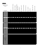
10 16 2.44 1.4 1.7 N22 LP16 N22 26 26 11.7 7 14 LP NAT LP NAT LP NAT LP NAT LP NAT LP NAT LP NAT LP NAT LP G31 G20 G31 G20 50 18/20 50 18/20 I3P I2H I3P I2H 16 16 1.15 1.75 1.15 1.7 15.2 23.3 27.2 27.8 G20 G31 G20 G37 G20 G37 20 37/50 20 37 20 37 I2H I3P II2H3P II2H3P II2H3P II2H3P 10.8 29.4 6.2 15.3 6.8 19 2.44 1.51 4.16 2.18 4.4 2.18 LP16 N22 LP16 N22 LP16 N22 LP16 18 (PM)(PR)14 (R) RPB14A RPB14B 12 24 34 G20 G31 G20 20 37 18/20 I2H I3P I2H 10 16 2.44 1.4 1.
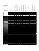
2.44 1.4 1.7 N22 LP16 N22 26 26 11.7 7 14 LP NAT LP NAT LP NAT LP NAT LP NAT LP NAT LP NAT LP NAT LP G31 G20 G31 G20 50 18/20 50 18/20 I3P I2H I3P I2H 16 16 1.15 1.75 1.15 1.7 15.2 23.3 27.2 27.8 G20 G31 G20 G37 G20 G37 20 37/50 20 37 20 37 I2H I3P II2H3P II2H3P II2H3P II2H3P 10.8 29.4 6.2 15.3 6.8 19 2.44 1.51 4.16 2.18 4.4 2.18 LP16 N22 LP16 N22 LP16 N22 LP16 18 (PM)(PR)14 (R) RPB14A RPB14B 12 24 34 G20 G31 G20 20 37 18/20 I2H I3P I2H 10 16 2.44 1.4 1.
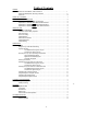
Table of Contents TABLES: Tables for Great Britain, Ireland & France . . . . . . . . . . . . . . . . . . . . . . . . . . . . i Tables for Netherlands, Germany & Austria . . . . . . . . . . . . . . . . . . . . . . . . . . . ii Tables for . . . . . . . . . . . . . . . . . . . . . . . . . . . . . . . . . . . . . . . . . . . . . . . . . iii . . . . . . . . . . . . . . . . . . . . . . . . . . . . . . . . . . . . . . . . . . . . . . .1 MODEL NUMBER RECOGNITION: . . . . . . . . . . . . . . . . . . . . . . . . .
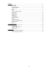
SERVICE: . . . . . . . . . . . . . . . . . . . . . . . . . . . . . . . . . . . . . . . . . . . . . . . . . . . . . . . .8 Thermostats . . . . . . . . . . . . . . . . . . . . . . . . . . . . . . . . . . . . . . . . . . . . . . . . 8 Gas Valves . . . . . . . . . . . . . . . . . . . . . . . . . . . . . . . . . . . . . . . . . . . . . . . . 8 Hi Limit Thermostats . . . . . . . . . . . . . . . . . . . . . . . . . . . . . . . . . . . . . . . . . . 9 Thermocouples . . . . . . . . . . . . . . . . . . . . . . . . .
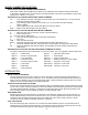
MODEL NUMBER RECOGNITION: EXPLANATION OF MODEL NUMBER CONFIGURATION: Most model numbers have a PREFIX and a SUFFIX. The explanation of the different Prefixes and Suffixes is listed below. Standard fryers, with NO options and a mild steel tank, will not have any PREFIX or SUFFIX but simply have a number (7, 14, 18 etc.) EXPLANATION OF PREFIXES WITHIN BASIC MODEL NUMBERS: PR = Fryer utilizing a solid state T-Stat (GO) control and melt cycle.
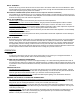
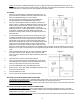
INITIAL ASSEMBLY: Remove the two (2) screws that mount the rear of the tank to the cabinet. Place the Flue Heat Deflector in place with the bend facing forward. Replace the tank mounting screws, through the Flue Heat Deflector into the tank. In some cases the fryers legs may need to be installed. ELECTRICAL CONNECTIONS: (Some machines do not require an electrical connection) Pitco Frialators are manufactured to run on a particular electrical supply.
NOTE: On machines equipped with Digital Controls or Computers that are programmed with a melt cycle, the main burners will pulse on and off to slowly heat the oil. When the oil temperature has reached a preset level the main burners will run constantly until the set temperature has been reached. FILTERING: Filtering is recommended on a daily basis to keep the oil in as good a condition as possible. Follow the instructions below and refer to the appropriate Figure for your machine. Figure 1. 1.
OPERATING THE COMPUTER CONTROL: To check the ACTUAL Temperature Press the mode.) To check the SET Temperature Press the mode.) key (After 5 seconds the display will return to the run key two times. (After 5 seconds the display will return to the run key and the desired PRODUCT NUMBER To check the COOK, SHAKE or HOLD times press the key. (The times will be automatically displayed in sequence, the display will return to the run mode.
CLEANING / MAINTENANCE: DAILY CLEANING: Using a soft cloth and a mild detergent, wipe all external surfaces until they are free of debris. It is permissible to allow a thin film of cooking oil to remain on all exposed (NON PAINTED) surfaces. Be sure to clean the front panel and behind the door. WEEKLY CLEANING: Turn the gas valve knob to the PILOT position. The fryer should be completely drained of shortening. Fill the fry tank with water to above the minimum and below the maximum level lines.
TROUBLESHOOTING: FRYING SYSTEM: Should there be a problem with your machine, the following checks should be done prior to calling an Authorized Service Company. Make sure the machine is operated correctly and that the Computer or Digital Display (when installed) is programmed accordingly.
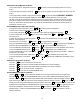
FILTERING SYSTEM: Check these items before calling your Authorized Service Company PROBLEM CHECK Power to machine Check main power to the machine Circuit breaker Check filter circuit breaker on side of filter handle Motor overheat trip Remove cap on the left side at the rear of filter and push red button Shortening return quick disconnect Fitting should be tight and clean Pick up tube Steel nut should be tight on the filter Pick up screen inside tube should be clear Fitting at top of tube should
Hi Limits Thermostats: All Hi Limits are electric switches that OPEN at a pre determined temperature. Check for continuity across the terminations when the wires are disconnected. Thermocouples: Use a Multi Meter capable of measuring DC voltage below 1V. Attach the Negative lead to the Pilot Bracket and the Positive lead to the upper connection at the Hi Limit. Light the Pilot and measure the DC voltage. The voltage should be 25-35 mv.
connections for integrity If the connection is good the Probe should be checked as described in the appropriate section. If the Probe is not at fault the computer may be suspect. { If the display is lit but the Main Burners are still controlled by the Alternate Thermostat, check for 24 vdc at the K5 relay. This relay is the Control Transfer Relay and is energized at all times when the computer is ON.
TROUBLE SHOOTING: v v v v v Before diagnosing any machine for defective components check the following items: Check all power cords and appropriate circuit breakers to ensure that electrical power is supplied to the machine. Check all machine gas shut off valves to ensure that gas is supplied to the machine. Check all machine fuses. Check any appropriate electrical connections within the machine. Check all appropriate switches and gas valve knobs to ensure that machine is operated correctly.
RPB14: SYMPTOM POSSIBLE CAUSES Blower comes ON but Burners do NOT light. Defective HSI. Defective HSI module. HSIs blow but Burners do NOT come on. Defective HSI module. Burners come ON but shut down after a few seconds. Defective HSI module. Defective HSI. Defective Burner. Incorrect Gas or Air pressure. Burners try to ignite but Blower does NOT come on. Defective Blower Relay. Defective Blower. Machine makes Booming sound. Defective HSI. Defective HSI module.
PARTS LIST: NOMENCLATURE A1 A1 A1 A1 A1 A2 A2 & A3 E1 E2 F1 & F2 F3 I1 & I2 J1 J2 & J15 J3, J8 & J11 J4, J5, J7 & J10 J6 J14 K1, K2, K4 & K5 K3 K4 K6 M1 M2 M3 M3 P1 P2 & P15 P3, P8 & P11 P4, P5, P7 & P10 P6 P12 P14 S1 & S3 S1 & S4 S2 & S3 S2, S4 & S7 S5 & S6 S7 T1 T2 V1 V1 V1 DESCRIPTION Cooking Controller Cooking Controller Cooking Controller Cooking Controller Cooking Controller Electronic Ignition Module Ignition Control Module Flame Sensor Pilot/Ignitor Assembly Fuse, 4 Amp Slow Blow Fuse, 1 Amp Slow B