テーブルトップスタンド Table top stand Support de couverture de table Tischgestell Supporto di tavolo Tafel staander Table top stand Soporte de mesa 臺式支架 PDK-TS01 PDK-TS01-L 取扱説明書 Operating instructions Mode d’emploi Bedienungsanleitung Istruzioni per l’uso Gebruiksaanwijzing Bruksanvisning Manual de instrucciones 操作說明書
ご使用の前に 取扱上の注意 このたびは、パイオニアの製品をお買い求めいただき、まこ とにありがとうございます。お使いになる前にこの取扱説明 書をよくお読みの上、 「取扱上の注意」に従い、正しくお使 いください。お読みになったあとは、後々お役に立つことも ありますので大切に保存してください。 1. 本製品は弊社製プラズマディスプレイ専用のテーブル トップスタンドです。 2. 指定外のプラズマディスプレイへの取り付けや改造およ び他の用途への使用はしないでください。 3. 取り付け等に不具合があると転倒などの事故につながり 大変危険です。プラズマディスプレイ本体への取り付け は、必ずプラズマディスプレイを寝かせた状態で行って ください。 4. 設置場所について (イ) 設置場所にはスタンドとディスプレイの重量に十分 耐えられる強度をもつ場所を選定してください。 (ロ) 設置場所は、水平、平面で安定しており、荷重が均 等にかかるよう注意して設置してください。 (ハ) 屋外や温泉、海辺の近くには設置しないでください。 (ニ) 振動や衝撃の加わるような場所には設置しないでく ださい。 5.
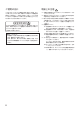
日本語 ■ 構成部品の確認 • ベースカバー .............. 1 • スタンドパイプ(L, R 共通)...... 2 • 取り付けボルト 1 (M8 × 20) ................. 2 • ネジ (4 × 8) ........ 4 • 取り付けボルト 2 (M8 × 40) ................. 2 • 六角レンチ .......... 1 • 転倒防止用ボルト .... 2 1. スタンドの組み立て ■ 組み立て手順 1. ベースカバーを裏側にする。 2. スタンドパイプ をベースカバーに挿入する。 3.
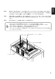
2. 本体への取り付け ■ 通常の取り付け方法 手順 1 プラズマディスプレイを寝かせた状態にして、取り付けボルト 1(M8 × 20)2 本を、プラ ズマディスプレイ本体の穴 a に取り付ける。 このとき、横から見て、取り付けボルト 1 のネジ部が見えなくなったところで、ネジ止めを やめてください。 (最後までネジ止めすると、 スタンドパイプの取り付けができなくなります。 ) 取り付けボルト 1(M8 × 20) 穴a (プラズマディスプレイ 中央部の穴) 取り付けボルト 1 プラズマ ディスプレイ本体 ネジ部が見えなくなったと ころでネジ止めをやめる。 プラズマディスプレイ本体 ◆ テーブルトップスタンド側で使用するスタンドパイプのネジ穴について 表 .
表に従い、取り付けボルト1のネジ頭にスタンドパイプの穴(A, Bの何れか)を引っ掛けて、 スタンドをプラズマディスプレイ本体上方向にスライドさせ、取り付けボルト 1 に突き当て てください。 (スライド量は、スタンドの構造上、19mm 以下となります。 ) 手順 3 付属の六角レンチを使用して、取り付けボルト 2(M8 × 40)2 本で、スタンドをプラズマ ディスプレイ本体にネジ止めする。 (使用する穴の組み合わせは、Aー A'、Bー B' の 2 通り です。) 手順 4 取り付けボルト 1 を付属の六角レンチで締め付ける。 1. 2. 3. 4. ご注意 5.
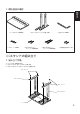
■ プラズマディスプレイ本体の梱包材を置台として使用する方法 (イラストは50型のものです) ◆ プラズマディスプレイ本体の梱包箱の構成 外箱 中箱 パッド ミラーマット パッド プラズマディスプレイ本体 手順 1 上図に示した中箱とパッドを使い、プラズマディスプレイの置き台を作ります。 (パッドは全 て同じです) パッド 中箱 手順 2 パッドの上にプラズマディスプレイ本体を下図のように置きます。 プラズマディスプレイ本体 ミラーマット 手順 3 6 中箱の上にパッドを 2 つ置いた台 “通常の取り付け方法”の手順 1 ∼手順 4 に従って、スタンドをプラズマディスプレイ本体に 取り付けます。
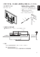
■転倒防止用ボルトの使用例 (イラストは50型のものです) ■床に固定する方法 ●市販のネジを使って止める 1. プラズマディスプレイ本体に付属の転倒防止用ボルトを つける。 2. 壁または柱に丈夫なヒモで固定する。 (左右対称に同様の作業を行ってください。 ) ヒモ及びフックは市販のものをお使いください。 1 2 ■ 床固定ネジ取付座標 ※床に固定する際のネジは、M6、長さ 20mm 以上のものを使用してください。 単位:mm 485 (50 型) 411 (43 型) 11.5 275 64 248 ■ 仕様 外形寸法 ...................................... 566 (幅) x 508 (高) x 339 (奥行) mm 質量 ............................................ 4.0 kg ............................................ 42.9 kg(50 型プラズマディスプレイ取り付け時) 35.
■ 寸法図 単位:mm 50 型通常使用時(スピーカーなし) 220 508 150 774 1218 566 339 50 型本体両サイドにスピーカー取り付け時 1368 スピーカー 1218 508 220 150 774 スピーカー 566 8 339
日本語 43 型スピーカーなし 508 685 220 150 1070 566 339 43 型本体両サイドにスピーカー取り付け時 1220 220 508 685 スピーカー 150 スピーカー 339 566 43 型本体下側にスピーカー取り付け時 508 732 267 150 1070 スピーカー 566 339 2001パイオニア株式会社 禁無断転載 9
Thank you for buying this Pioneer product. Please read through these operating instructions so you will know how to operate your model properly. After you have finished reading the instructions, put them away in a safe place for future reference. CAUTION Cautions 1. 2. 3. This symbol refers to a hazard or unsafe practice which can result in personal injury or property damage. Installation 4. ¶ Consult your dealer if you encounter any difficulties with this installation.
English 7 Check That You Have All the Parts • Base cover .................. 1 • Stand pipes (left and right, interchangable) .... 2 • Installation bolts 1 (M8 x 20) ...................... 2 • Screws (4 x 8) ........... 4 • Installation bolts 2 (M8 x 40) ........................ 2 • Hexagonal wrench ................................ 1 • Stabilization bolts ................................ 2 1. Stand assembling 7 Assembling Steps 1. 2. 3. Turn the base cover over so the underside is facing up.
2. Stand attaching to the Plasma Display 7 Normal Installation Step 1. With the plasma display lying flat, insert and secure the two Installation bolts 1 (M8 x 20) in the holes "a" located in the plasma display housing. At this point, tighten these bolts 1 only until the threads are no longer visible when viewed from t he side (you will be unable to attach the display if the bolts are screwed in completely).
As shown in figure, hook the stand pipe holes (either pipe A or B) onto the screw heads of the installation bolts 1, then slide the stand upwards to the main plasma display until it engages the installation bolts 1 (once put together with the display, the stand will slides no more than 19 mm (3/4 inch)). Step 3.
7 Instructions for using the main display packing material as a stand for the working on the display (50” display model is shown in the figure.) • Main plasma display packaging setup Outer box Inner box frame Pad Mirror mat Pad Plasma display Step 1. Construct the stand for the plasma display using the inner box frame and pads shown in the figure above (all pads are identical). Pads Inner box frame Step 2. Set the plasma display down on the pads as shown in the figure below.
3. After assembling, connect the stand to the floor to prevent from falling over. ¶ Use screws (sold separately) to attach and stabilize the stand. 7 Sample use of the stabilization bolts (50” display model is shown in the figure.) 1. 2. Attach the stabilization bolts that come with the plasma display. Stabilize the display by connecting to a wall or standing beam with a strong cord. (Repeat the same steps in the laterally direction to stabilize the assembly to the left and right.
7 Dimensions Diagram Units: mm (inch) 50" display under normal use (without optional speakers) 508 (20) 220 (8-21/32) 150 (5-29/32) 774 (30-15/32) 1218 (47-15/16) 566 (22-9/32) 339 (13-11/32) 50" display with optional speakers attached to both sides of display 1368 (53-27/32) 150 (5-29/32) 220 (8-21/32) 508 (20) Speaker 1218 (47-15/16) 774 (30-15/32) Speaker 566 (22-9/32) 16 339 (13-11/32)
43" display without optional speakers English 508 (20) 220 (8-21/32) 150 (5-29/32) 685 (26-31/32) 1070 (42-1/8) 339 (13-11/32) 566 (22-9/32) 43" display with optional speakers attached to both sides of display 1220 (48-1/32) 508 (20) 220 (8-21/32) 150 (5-29/32) Speaker 685 (26-31/32) Speaker 566 (22-9/32) 339 (13-11/32) 43" with optional speakers attached at bottom of display Speaker 566 (22-9/32) 508 (20) 267 (10-1/2) 732 150 (5-29/32) 1070 (48-1/32) 339 (13-11/32) Published by P
Merci d’avoir choisi ce produit pioneer. Nous vous invitons à lire les informations utiles à l’utilisation et à l’installation de ce produit. Apres avoir lu attentivement ces instructions, ranger les soigneusement afin de vous en servir pour de futures références. Attention 1. 2. Attention Ce signe symbolise un risque ou un danger qui peut provoquer des blessures ou des dégâts matériels. 3. Installation ¶ Consultez votre distributeur si vous rencontrez quelque difficulté avec cette installation.
• Couverture de base .... 1 • Piliers du support (gauche et droite semblables) ..... 2 • Boulons d’installation 1 (M8 x 20) ...................... 2 • Vis (4 x 8) ................... 4 • Boulons d’installation 2 (M8 x 40) ........................ 2 Françias 7 Vérifiez que vous avez toutes les pièces • Clé hexagonale ................................ 1 • Boulons de stabilisation ................................ 2 1. Assemblement du support 7 Etapes d’assemblement 1. 2. 3.
2. Support de l’affichage de plasma 7 Installation normale Etape 1. Avec l’affichage de plasma se trouvant à plat, insérez et fixez les 2 boulons d’installation 1 (M8x20) dans les trous "a" situés dans le logis de l’affichage de plasma. A ce point, serrez ces boulons 1 seulement jusqu’à ce que les amorçages ne soient plus visibles, vu du côté (Vous ne pourrez pas attacher l’affichage si les boulons sont complètement vissés).
Comme représenté sur la figure, accrochez les trous de piliers du support (tube A ou bien B) sur les têtes de vis des boulons d’installation 1. Puis glissez le support vers le haut à l’affichage de plasma principal jusqu’à ce qu’il engeance les boulons d’installation 1 (une fois assemblé avec l’affichage, le support ne glissera pas plus de 19 mm). Etape 3.
7 Instructions pour l’usage du matériel d’emballage de l’affichage principal comme un support pour le travail sur l’affichage (L’écran de 50 pouces est présenté sur la figure) • Empaquetage de l’affichage principal de plasma Boîte externe Cadre de boîte intérieure Garniture Natte de miroir Garniture Affichage de plasma Etape 1. Construisez le support pour à l’aide du cadre de boîte intérieure et des garnitures représentées sur la figure ci-dessus (toutes les garnitures sont identiques).
3. Après le rassemblement des différentes parties, reliez le support au sol afin d’éviter sa chute. ¶ Utilisez des vis (vendues séparément) pour rattacher et fixer le support. 7 Modèle d’utilisation des boulons de fixatio (le modèle de 50 pouces est représenté sur la figure) 1. 2. Attachez les boulons de fixation fournis avec l’écran plasma. Fixez l’affichage en le reliant à un mur ou un faisceau vertical à l’aide d’une corde solide.
7 Dimensions du schéma Unités: mm L’écran de 50 pouces sous utilisation normale (sans haut-parleurs optionnels) 220 508 150 774 1218 566 339 L’écran de 50 pouces avec haut-parleurs optionnels fixés aux deux côtés de l’écran 1368 Haut-parleur 1218 508 220 150 774 Haut-parleur 566 24 339
L’écran de 43 pouces sans haut-parleurs optionnels Françias 508 685 220 150 1070 566 339 L’écran de 43 pouces avec haut-parleurs optionnels fixés aux deux côtés de l’écran 1220 Haut-parleur 220 508 150 685 Haut-parleur 566 339 L’écran de 43 pouces avec haut-parleurs optionnels fixés au bas de l’écran 508 732 267 150 1070 Haut-parleur 566 339 Publication de Pioneer Corporation. © 2001 Pioneer Corporation. Tous droits de reproduction et de traduction réservés.
Wir bedanken uns bei Ihnen für den Kauf dieses Pioneer Produktes. Bitte lesen Sie diese Bedienungsanleitung aufmerksam durch um Ihr Produkt entsprechend benutzen zu können. Nachdem Sie die Bedienungsanleitung gelesen haben, legen Sie sie beiseite. Vorsicht 1. 2. Vorsicht Dieses Symbol weist auf Gefahr oder unsicheren Gebrauch hin, was zu Verletzungen und Schaden führen kann. Installation ¶ Bei Schwierigkeiten bei der Installation wenden Sie sich bitte an Ihrem Händler.
7 Kontrollieren Sie, daß Sie über alle Komponenten verfügen • Schrauben (4 x 8) ...... 4 • Gestellröhre (links und rechts, umsetzbar) ....... 2 • Senkkopfschrauben zur Installation 1 (M8 x 20) ...................... 2 • Hexangulärer Schraubenzieher ................................ 1 • Senkkopfschrauben zur Installation 2 (M8 x 40) ........................ 2 • Senkkopfschrauben zur Stabilization .............. 2 1. Der Zusammenbau des Gestells 7 Schritte des Zusammenbaus 1. 2. 3.
2. Anschluß des Gestells an das Plasma Display 7 Normal Installation Schritt 1. Wenn das Plasma Display waagrecht liegt, sollen Sie die zwei Senkkopfschrauben zur Installation 1 (M8 x 20) in den Klemmen "a" befindlich an dem Gehäuse des Plasma Displays anschließen und befestigen. Da sollen Sie die Schrauben solange ziehen bis der Gang von der Seite nicht zu sehen ist (Sie können das Display nicht anschließen wenn die Senkkopfschrauben völlig eingedreht sind).
Schritt 2. Laut der Abbildung hängen Sie die Löcher der Gestellsröhre (entweder Rohr A oder Rohr B) an den Köpfen der Senkkopfschrauben zur Installation 1, dann schieben Sie das Gestell in Richtung Plasma Display bis zu den Senkkopfschrauben zur Installation 1. (Nachdem Sie das Gestell an das Plasma Display angeschlossen haben, wird das Schieben des Gestells höchstens 19 mm). Schritt 3.
7 Instruktionen zur Benutzung des Packungsmaterials vom Display als Unterlage für die Arbeit am Display (In der Abbildung ist das 50”-Bildschirmmodell zu sehen.) • Zusammenbau der Packung vom Plasma Display Karton Inneres Gestell des Kartons Stopfung Spiegelfolie Stopfung Plasma Display Schritt 1. Bauen Sie die Unterlage mit Hilfe des inneren Gestells des Kartons und der Stopfungen für das Plasma Display zusammen nach der Abbildung (siehe oben) (alle Stopfungen sind identisch).
3. Befestigen Sie das Gestell nach dem Zusammenbau zum Boden um die Umstürzung zu vermeiden. 7 Befestigung zum Boden ¶ Benutzen Sie Schrauben (separiert erhältlich) zum Anschluß und zur Befestigung des Gestells. 7 Mustergebrauch der Stabilisierungsschrauben (In der Abbildung ist das 50”Bildschirmmodell dargestellt.) 1. 2. Die mit dem Plasmabildschirm mitgelieferten Stabilisierungsschrauben befestigen. Befestigen Sie das Display mit einem starken Draht zur Wand oder einem Gestell.
7 Diagramm der Abmessungen Einheiten: mm 50”-Bildschirms bei normalem Gebrauch (ohne die wahlweise mitgelieferten Lautsprecher) 220 508 150 774 1218 566 339 50”-Bildschirm mit den an den beiden Seiten des Bildschirms montierten wahlweise mitgelieferten Lautsprechern 1368 Lautsprecher 1218 508 220 150 774 Lautsprecher 566 32 339
43”-Bildschirm ohne die wahlweise mitgelieferten Lautsprecher 508 685 220 150 1070 566 339 1220 Lautsprecher 220 508 150 685 Lautsprecher Deutsch 43”-Bildschirm mit den an den beiden Seiten des Bildschirms montierten wahlweise mitgelieferten Lautsprechern 566 339 43”-Bildschirm mit den an der Unterseite des Bildschirms montierten wahlweise mitgelieferten Lautsprechern 508 732 267 150 1070 Lautsprecher 566 339 Veröffentlicht von Pioneer Corporation.
La ringraziamo per aver acquistato questo prodotto di Pioneer. La preghiamo di leggere attentamente le istruzioni di uso per sapere come usare corettamente il suo modello. Dopo di aver letto le istruzioni, metterle in un posto sicuro per un futuro riferimento. Avvertenze Avvertenze 1. 2. Questo simbolo si riferisce ad uso pericoloso che puó risultare danni personali o deterioramenti. 3. Installazione 4. ¶ Rivolgersi al proprio rivenditore in qualsiasi caso di difficoltá durante l’installazione.
7 Verificare se avete tutte le parti • Viti (4 x 8) ................... 4 • Rotaie del supporto (di destra e di sinistra cambiabili fra loro) ........... 2 • Ribattini di installazione 1 (M8 x 20) ...................... 2 • Brugola ..................... 1 • Ribattini di installazione 2 (M8 x 40) ........................ 2 • Ribattini di stabilire ... 2 Italiano • Copertura di base ....... 1 1. Montaggio del supporto 7 Montaggio 1. 2. 3. Girare la copertura di base con la parte inferiore sopra.
2. Attacamento del supporto al Display di Plasma 7 Installazione normale Passo 1. Con il display di plasma appoggiato in orizontale inserire e fissare i due ribattini di installazione 1 (M8x20) nei fori "a" situati nella copertura del display di plasma. A questo punto serrare i ribattini 1 finché non siano piú visibili dalla vista laterale (non é possibile attacare il display se i ribattini sono completamente avvitati).
Passo 2. Come mostra la figura, ganciare le teste di vite dei ribattini di installazione nei fori (guide A oppure B) delle rotaie, quindi far scorrere il supporto verso il principale display di plasma finché non si inseriscano i ribattini di installazione 1 (una volta messisi insieme con il display, il supporto non scorrerá piú di 19 mm) Passo 3. Far passare i ribattini per le rotaie e serrare sicuramente i ribattini con la brugola fornita (usare i fori nelle combinazioni corrette: A–A' e B–B').
7 Istruzione per usare l’incartamento come appoggio a lavorare sul display (Il display modello 50” é mostrato sul disegno) • Montaggio del pacco del display di plasma Pacco esterno La sistemazione di pacco di dentro Appoggi Mirror mat Appoggi Display di plasma Passo 1. Costruire il supporto per il display di plasma usando la sistemazione del pacco e gli appoggi mostrati in figura di sotto (Tutti gli appoggi sono identici). Appoggi La sistemazione di pacco di dentro Passo 2.
3. Dopo il montaggio impostare il supporto sul pavimento per evitare la caduta 7 Stabilire sul pavimento ¶ Usare viti (non forniti) per attacare e stabilire il supporto. 7 Modello d’uso dei ribattini di stabilizzazione (Il display modello 50” é mostrato sul disegno) 1. 2. Attaccare i ribattini di stabilizzazione forniti al display al plasma. Stabilire il display collegandolo al muro o posizionandolo con una forte corda.
7 Diagramma di dimensione Unitá: mm Il display modello 50” durante l’uso normale (senza altoparlanti opzionali) 220 508 150 774 1218 566 339 Il display modello 50” con altoparlanti opzionali attaccati a tutti idue lati del display 1368 L’altoparlante 1218 508 220 150 774 L’altoparlante 566 40 339
Il display modello 43” senza altoparlanti opzionali 508 685 220 150 1070 566 339 Il display modello 43” con altoparlanti opzionali attaccati a tutti idue lati del display 1220 Italiano L’altoparlante 220 508 150 685 L’altoparlante 566 339 Modello 43” con altoparlanti opzionali attaccati al basso del display 508 732 267 150 1070 L’altoparlante 566 339 Pubblicato da Pioneer Corporation. Copyright © 2001 Pioneer Corporation. Tutti i diritti reservati.
Dank u wel voor het kopen van dit Pioneer produkt. Lees alstublieft deze gebruiksaanwijzing door zodat u weet hoe u uw model op een juiste manier moet laten functioneren. Nadat u de instructies gelezen heeft, zet ze op een veilige plaats voor latere verwijzing. WAARSCHUWINGEN 1. 2. WAARSCHUWING Deze symbool duidt een gevaarlijke of onjuiste functionering aan dat kan persoonlijke verwonding of schade in het produkt veroorzaken.
7 Controleer of u alle delen heeft • Voetstuk ..................... 1 • Schroeven(4 x 8) ....... 4 • Poten van de staander (links en rechts verwisselbaar) .... 2 • Installatie schroeven 1 (M8 x 20) ...................... 2 • Zeshoekige draai ..... 1 • Installatie schroeven 2 (M8 x 40) ........................ 2 • Stabiliseringsschroeven ................................. 2 1. Samenstelling van de staander 1. 2. 3.
2. Staander aan het plasmascherm voegen 7 Normale installatie Stap 1. Terwijl het plasmascherm neerligt, zet en verveilig de twee installatie schroeven 1 (M8x20) in gaten "a" die op het omhulsel van het plasmascherm verplaatst zijn. Bij dit punt draai deze schroeven 1 alleen aan totdat de draailijnen van het zijdegezien al niet meer zichtbaar zijn (Als u de schroeven volledig indraait is het onmogelijk om het plasma scherm eraan te voegen).
Stap 2. Zoals het figuur het laat zien, haak de gaten van de staanderpoten (A of B in beide buizen) aan de schroefkoppen van de installatie schroeven 1, daarna laat de staander boven glijden in de richting van het plasmascherm totdat het de installatie schroeven 1 aanraakt (als het met het scherm samengesteld is, zal de staander niet meer dan 19mm glijden.) Stap 3.
7 Instructies voor het gebruik van de verpakking van het hoofdscherm om het als staander laten functioneren (de figuur toont het beeldscherm van 50") • De werking van het plasmascherm verpakking Buitendoos Binnenste lijst van doos Opvulsel Spiegelbescherming Opvulsel Plasmascherm Stap 1. Stel een staander voor het plasmascherm samen, gebruik de binnenste lijst van de doos en de opvulsels volgens het bovenstaande figuur (alle opvulsels zijn hetzelfde). Opvulsel Binnenste lijst van doos Stap 2.
3. Nadat de staander samengesteld is, maak de staander aan de vloer vast zodat het niet omvalt. 7 Stabilisering aan de vloer ¶ Gebruik schroeven (worden apart verkocht) voor het aanvoegen en stabiliseren van de staander. 7 Toepassingsvoorbeeld van de stabilisatieschroeven (de figuur toont het beeldscherm van 50") 1. 2. Monteer de bij het plasmascherm geleverde stabilisatieschroeven. Stabiliseer het scherm door het aan de muur verbinden of met een serke touw tegen een balk vastmaken.
7 Diagram van dimensie Uenheid: mm Beeldscherm van 50" bij normaal gebruik (zonder afzonderlijk leverbare luidsprekers) 220 508 150 774 1218 566 339 Beeldscherm van 50" met aan weerszijden gemonteerde, afzonderlijk leverbare luidsprekers 1368 Luidspreker 1218 508 220 150 774 Luidspreker 566 48 339
Beeldscherm van 43" zonder afzonderlijk leverbare luidsprekers 508 685 220 150 1070 566 339 Beeldscherm van 43" met aan weerszijden gemonteerde, afzonderlijk leverbare luidsprekers 1220 Luidspreker 220 Nederlands 508 150 685 Luidspreker 566 339 Beeldscherm van 43" met aan de onderzijde van het scherm gemonteerde, afzonderlijk leverbare luidsprekers 508 732 267 150 1070 Luidspreker 566 339 Uitgegeven door Pioneer Corporation. Copyright © 2001 Pioneer Corporation.
Tack för ni har köpt denna Pioneer produkt. Vänligen läs igenom dessa instruktioner så att ni vet hur ni ska använda er modell på rätt sätt. Efter ni har läst igenom instruktionerna, lägg undan dom på ett säkert ställe ifall de kan behövas i framtiden. VARNING Denna symbol vill göra er uppmärksam på att iakta försiktighet så att inte skada uppstår. VARNING 1. 2. 3. 4. Installation ¶ Rådgör med er försäljare om svårigheter uppstår vid installationen.
7 Kontrollera att ni har all delar • Bottenskydd ............... 1 • Skruvar (4 x 8) ........... 4 • Ställningsrör (vänster och höger, utbytbara) .... 2 • Installationsbultar 1 (M8 x 20) ...................... 2 • Hexagonal skruvnyckel ................................ 1 • Installationsbultar 2 (M8 x 40) ........................ 2 • Stabiliseringsbultar ................................. 2 1. Ställning Hopsättning 7 Steg för hopsättning Vänd bottenskyddet med undersidan upp.
2. Fastsättning av ställningen till Plastpanelen 7 Normal Installation Steg 1. När plastpanelen ligger rakt ner, för in och försäkra de två installtionsbultarna 1 (8 x 20) i hålen "a" i plastpanelens hölje. Skruva dessa bultar 1 ändast så långt att inte tråden år synlig från sidan (om bultarna skruvas för hårt kan inte panelen sättas på). Installationsbultar 1 (M8 x 20) Hål "a" (hålen i mitten av plasmaskärmen) Installationsbult 1 Plastpanel hölje Sluta skruva ner bulten när trådarna inte längre syns.
Steg 2. Se figur, haka hållen på ställningsrören (antingen rör A eller B) på installationsbultarnas skruvhuvuden 1. Skjut sedan ställningen uppåt till huvud plastpanelen tills den hakar i installationsbultarna 1. (hopsatt ställning glider inte mer än 19 mm). Steg 3. Skjut installationsbultarna 2 (M8x40) genom ställningsrören och dra till installationsbultarna med medföljande hexagonal skruvnyckel (Hålen ska kombineras rätt, A–A’ och B–B’). Steg 4.
7 Instruktioner för användning av huvudpanelens förpackningsmaterial som ställning vid arbete på panelen. (Bilden visar 50" skärmen.) • Uppsättning av förpackningsmaterial till hunvud plastpanelen Yttre box Innre box ram Dyna Spegelmatta Dyna Plastpanel Steg 1. Kontruera ställningen för plastpanelen genom att använda den innre boxens ram och dyna enligt bild ovan (alla dynor är identiska). Dyna Innre box ram Steg 2. Sätt ner plastpanelen på dynorna enligt figuren nedan.
3. Efter hopsättning, sätt fast ställningen i golvet för att förhindra att den ramlar. 7 Fastsättning i golvet ¶ Använd skruvar (säljs separat) för att sätta fast ställningen. 7 Exempel på användning av stabiliseringsskruvarna. (Bilden visar 50" skärmen) 1. 2. Satt fast stabiliseringsskruvarna som medföljer skärmen. Stabilisera panelen ganom att stödja den mot en vägg.
7 Dimensions Diagram Enhet : mm 50" skärmen under normal användning (utan tillvalbara högtalare) 220 508 150 774 1218 566 339 50" skärm med tillvalbara högtalare monterade på båda sidorna av skärmen 1368 Högtalare 1218 508 220 150 774 Högtalare 566 56 339
43" skärm utan tillvalbara högtalare 508 685 220 150 1070 566 339 43" skärm med tillvalbara högtalare monterade på båda sidorna av skärmen 1220 Högtalare 220 508 150 685 Högtalare 566 Svensk 339 43" med tillvalbara högtalare monterade under skärmen 508 732 267 150 1070 Högtalare 566 339 Published by Pioneer Corporation. Copyright © 2001 Pioneer Corporation. All rights reserved.
Gracias por haber comprado este producto Pioneer. Le rogamos repase estas instrucciones para saber manejar su modelo correctamente. Después de leer las instrucciones, guárdelas en un lugar seguro para utilizarlas como referencia en el futuro. Precauciones 1. 2. PRECAUCIÓN Este símbolo refiere a peligros o a práctica peligrosa que puede causar lesiones personales o daños materiales. 3. Instalación ¶ Si se le presentaran dificultades en cuanto a la instalación, consulte con el distribuidor del producto.
7 Verifique que no faltan accesorios • Placa de base ............. 1 • Tornillos (4 x 8) .......... 4 • Tubos del soporte (Izquierdo y derecho, intercambiables) ........... 2 • Pernos de instalación 1 (M8 x 20) ...................... 2 • Llave hexagonal ...... 1 • Pernos de instalación 2 (M8 x 40) ........................ 2 • Pernos de estabilización ................................. 2 1.
2. Ajuste del soporte a la pantalla plasma 7 Instalación normal Paso 1. Colocando la pantalla plasma en una superficie llana, inserte y fije ambos pernos 1 (M8x20) en los agujeros "a" situados en el dorso de la pantalla plasma. Entonces, apriete los pernos 1 justamente hasta que ya no se vean las roscas si las miramos de lado (si los pernos se atornillan completamente, no dejarán ajustar la pantalla).
Paso 2. Enganchar los agujeros de los tubos del soporte (bien el tubo A o B) en las cabezas de los pernos de instalación 1, luego resbalar el soporte hacia arriba, en dirección de la pantalla plasma hasta que se engrane con los pernos de instalación 1, según lo mostramos en la figura (una vez compuestos el soporte y la pantalla, no se resbalarán más de 19 mm). Paso 3.
7 Instrucciones para utilizar el embalaje de la pantalla como soporte para el trabajo con la misma (En la figura se muestra el modelo de pantalla de 50”) • Montaje del soporte de embalaje Caja exterior Marco interior de la caja Cojín de relleno Capa del espejo Cojín de relleno Pantalla plasma Paso 1. Construya el soporte para la pantalla plasma utilizando el marco interior y los cojines de la caja mostrados en el dibujo de arriba (todos los cojines son idénticos).
3. Después de montar el soporte, conéctelo al suelo para evitar que se caiga. 7 Fijación al suelo ¶ Utilice tornillos (vendidos por separado) para fijar y estabilizar el soporte. 7 Cómo utilizar los pernos de estabilización (en la figura se muestra el modelo de pantalla de 50”) 1. 2. Instale los pernos de estabilización suministrados con la pantalla de plasma. Estabilice la pantalla conectándolo a una pared o un poste por medio de una cuerda fuerte.
7 Diagrama de dimensiones Unidades: mm Pantalla de 50” en condiciones de uso normales (sin altavoces opcionales) 220 508 150 774 1218 566 339 Pantalla de 50” con altavoces opcionales instalados en ambos lados de la pantalla 1368 Altavoz 1218 508 220 150 774 Altavoz 566 64 339
Pantalla de 43” sin altavoces opcionales. 508 685 220 150 1070 566 339 Pantalla de 43” con altavoces opcionales instalados en ambos lados de la pantalla 1220 Altavoz 220 508 150 685 Altavoz 566 339 Pantalla de 43” con altavoces opcionales instalados en la parte inferior de la pantalla Español 508 732 267 150 1070 Altavoz 566 339 Uitgegeven door Pioneer Corporation. Copyright © 2001 Pioneer Corporation. Alle rechten voorbehouden.
使用之前 使用注意事項 承蒙您購買先鋒產品,對此表示衷心地感謝。使用前請仔細閱 讀使用說明書,並根據“使用注意事項”正確操作。閱讀完後 請保存此說明書,以備日後使用。 1. 該產品為本公司等離子顯示器專用臺式支架。 2. 請不要用於指定以外的等離子顯示器的安裝、改造及其他 用途。 3. 安裝不當的話會導致翻倒等事故發生,非常危險。安裝到 等離子顯示器主體上時,請務必在等離子顯示器水平放置 狀態下進行。 4. 放置場所 (a) 請選擇能足夠支撐支架和顯示器重量的場所。 (b) 請使放置場所保持水平、穩定並注意負荷均勻。 (c) 請勿放置於屋外及溫泉、海邊附近。 (d) 請勿放置於有振動、沖擊的地方。 5.
7 組成零件的確認 • 底座 ............ 1 • 立管(左右通用).......... 2 • 固定螺栓 1 (M8 × 20).......... 2 • 螺釘(4 × 8)... 4 • 固定螺栓 2 (M8 × 40).......... 2 • 內六角扳手 ..... 1 • 防倒角型螺栓 ...... 2 1. 組裝支架 7 組裝步驟 1. 將底座底朝上放置。 2. 將立管插入底座。 3.
2. 安裝到主體上 7 通常的安裝方法 步驟 1 將等離子顯示器平放在桌面上,將兩個固定安裝螺栓 1(M8 × 20)安裝到等離子顯示器主體的 孔 a 中。這時,應將固定螺栓 1 擰緊到從側面看不到螺紋部位為止。(如果將螺栓一直擰到底 的話,則將無法安裝立管。) 固定螺栓 1(M8 × 20) 孔 a (等離子顯示器 中央的螺釘孔) 固定螺栓 1 等離子顯示器主體 擰緊到看不到螺紋部位為 止。 等離子顯示器主體 ◆ 關於臺式支架側使用的立管的螺釘孔。 表 .
步驟 2 如上表所示,將立管的孔(A或B)挂住螺栓#1#的頭部,使支架向等離子顯示器的上方滑動, 直到碰到固定螺栓 1 。(受支架構造限制,滑動幅度在 19mm 以下。) 步驟 3 使用附帶的內六角扳手,用兩個固定螺栓2(M8×40),把支架固定到等離子顯示器的主體上。 (使用孔的組合為 A , A' 和 B , B' 的兩種。) 注意 用附帶的內六角扳手 1 把固定螺栓固定好。 1. 2. 3. 4. 5.
7 將等離子顯示器的主體的包裝材料用作放置臺的安裝方法(插圖為50型 顯示器) ◆ 等離子顯示器的主體包裝箱的構成 外箱 中箱 墊片 薄膜墊 墊片 等離子顯示器的主體 步驟 1 如上圖所示,使用中箱和墊片,製作等離子顯示器的放置臺。(墊片完全相同) 墊片 中箱 步驟 2 如下圖所示把等離子顯示器放置於墊片上。 等離子顯示器的主體 薄膜墊 步驟 3 70 在中箱上放置兩個墊片後做成的臺子 請按照“通常的安裝方法”的步驟 1 4 ,把支架安裝在等離子顯示器的主體上。
3. 安裝後,固定在地板上,做好防倒的準備工作 7 防倒用螺栓的使用實例(插圖為 50型顯示器) 7 固定在地板上的方法 • 使用市售螺釘固定 1. 裝上等離子顯示器附帶的防倒螺栓。 2. 用結實的繩子固定在牆上或者柱子上。 (操作時,請對稱側也安裝防倒用螺栓。) 繩子以及掛鉤請使用市售產品。 1 2 7 地板固定螺釘的安裝坐標 固定在地板上的螺釘應使用 M6 型長度 20mm 以上的螺釘。 單位︰ mm 485(50 型等離子顯示器) 411(43 型等離子顯示器) 11.5 275 64 248 7 規格 中國語 外形尺寸 ...................... 566(寬)x 508(高)x 339(深)mm 質量 .......................... 4.0kg ....................... 42.9kg(安裝 50 型等離子顯示器時) 35.
7 尺寸圖 單位︰ mm 50 型顯示器通常使用時 220 508 150 774 1218 566 339 50 型顯示器主體兩側安裝揚聲器時 1368 揚聲器 1218 508 220 150 774 揚聲器 566 72 339
43 型顯示器不裝揚聲器時 508 685 220 150 1070 566 339 43 型顯示器主體兩側安裝揚聲器時 揚聲器 揚聲器 220 508 150 685 1220 566 339 43 型顯示器主體下側安裝揚聲器時 中國語 508 732 267 150 1070 揚聲器 566 339 日本先鋒公司出版 版權©2001日本先鋒公司 版權所有 73
この取扱説明書の印刷には 植物性大豆油インキを使用 しています。 この取扱説明書は再生紙を使用しています。 2001パイオニア株式会社 Published by Pioneer Corporation. Copyright © 2001 Pioneer Corporation. All rights reserved. 禁無断転載 153-8654 PIONEER CORPORATION 東京都目黒区目黒1丁目4番1号 4-1, Meguro 1-Chome, Meguro-ku, Tokyo 153-8654, Japan PIONEER ELECTRONICS (USA) INC. P.O.BOX 1540, Long Beach, California 90801-1540, U.S.A. TEL: 1-310-952-2111 PIONEER EUROPE NV Pioneer House Hollybush Hill, Stoke Poges, Slough SL2 4QP, U.K.