
User Manual


1
15
64
"
1
11
64
"
1
11
64
"
1
15
64
"
8
10
10
43
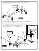
2.
distance between middle holes to side holes is different, see Front
View of Figure 2. Attach Stop Spools (#12) and Support Plates
(#43) to side of Caster Beam without logo with Bolts (#13) and Nuts
(#28) but do not tighten completely. See Figure 2.
Repeat step for second Caster Beam.
Lay Support Plates (#43) on Caster Beam (#8) to line up holes, the
13
28
43
12
8
Longer
Shorter
Figure 2
Front View
Longer
Shorter
Match Support Plate (#43)
with Caster Beam (#8).
holes in
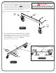
1A. Attach Caster Wheels (#9 & #10) to Caster Beam. Slide a Caster
Wheel with Lock (#10) through Caster Beam (#8) and secure it with a
Push Nut (#11) as shown in Figure 1. Gently tap the Push Nut (#11)
with a hammer to secure it in place. On the other end of the Caster
Beam attach a Caster Wheel without Lock (#9). Make sure you have
one Caster Wheel with Lock and a Caster Wheel without Lock for each
Caster Beam. Repeat step for second Caster Beam.
1B. Attach Tube Plugs (#14) to Caster Beam (#8) as shown in Figure 1.
Figure 1
Caster
with
Lock
Caster
without
Lock
9
10
11
14
3
8
READ AND FOLLOW ALL ASSEMBLY, OPERATING, AND
SAFETY INSTRUCTIONS CAREFULLY. AT LEAST TWO (2)
ADULTS ARE NEEDED TO PUT THIS TABLE TOGETHER!
CAUTION: