TABLE TENNIS TABLE MODEL NO. T8674 OWNER'S MANUAL 1. Read this manual carefully before starting assembly. Read each step completely before beginning each step. 2. Some smaller parts may be shipped inside larger parts. Check inside all parts and cartons before assembling or ordering parts. 3. To make assembly easier, use the Hardware Identifier on page 2 to identify and sort all fasteners. Check all cartons for kits. All hardware may not be located in one kit. 4.
HARDWARE IDENTIFIER 34 27 29 3/8-16 Nyloc Locknut (Qty. 12) 30 1/4-20 X 1 1/2 Phillips Truss Head Screw (Qty. 4) 1/4-20 X 2 3/4 Hex Head Bolt (Qty. 8) 32 31 1/4-20 X 3 1/4 Carriage Bolt (Qty. 4) 1/4-20 Wing Nut (Qty. 4) 37 35 #10-24 X 1/2 Phillips Pan Head Screw (Qty. 4) 1/4-20 Nyloc Locknut (Qty. 12) 3/8-16 x 3 1/2 Hex Head Bolt (Qty. 4) 28 23 5 #8 X 9/16 SMS (Qty. 180) 38 36 #8-32 X 1 1/4 Sheet Metal Screw (Qty. 4) 3/4" Long Spacer (Qty. 4) 39 3/8" Long Spacer (Qty.
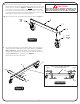
1A. Attach Caster Wheels (#9 & #10) to Caster Beam. Slide a Caster CAUTION: Wheel with Lock (#10) through Caster Beam (#8) and secure it with a Push Nut (#11) as shown in Figure 1. Gently tap the Push Nut (#11) READ AND FOLLOW ALL ASSEMBLY, OPERATING, AND with a hammer to secure it in place. On the other end of the Caster SAFETY INSTRUCTIONS CAREFULLY. AT LEAST TWO (2) ADULTS ARE NEEDED TO PUT THIS TABLE TOGETHER! Beam attach a Caster Wheel without Lock (#9).
3. Attach Wood Bottom Board (#15) to Caster Beam Assemblies (#8) as shown in Figure 3. Turn Caster Beams as shown and attach board with four Carriage Bolts (#31) and four Wing Nuts (#32). Tighten Thumb Screws securely. Note: Support Plate (#43) must be on inside of Caster Rail (#8) as shown. 31 43 8 15 31 8 32 Figure 3 32 4. Attach Strut Tubes (#17) and Linkages (#16) to Caster Beam Assemblies (#8) as shown in Figure 4.
. Lay Table Top (#1) painted side down, on a smooth, flat surface. Use the shipping container to protect the painted surface of table top. 6. Align the ”U” Support (#21) on Table Top (#1) as shown in Figure 5. CAUTION: WHEN ASSEMBLING TABLE, IT IS EXTREMELY IMPORTANT THAT THE U-CLIPS (#22) BE TURNED AS SHOWN HERE. IF U-CLIPS ARE TURNED INCORRECTLY, YOU WILL DO IRREPARABLE DAMAGE TO YOUR TABLE WHEN YOU ATTEMPT TO OPEN IT TO THE PLAYING POSITION. 7.
CAUTION: DO NOT USE A POWER DRIVER TO ATTACH HINGE BRACKET ASSEMBLIES (#18) YOU COULD STRIP SCREW IN WOOD AND DO IRREPARABLE DAMAGE TO THE TABLE. DO NOT OVER TIGHTEN SCREWS CAUSING THEM TO STRIP THE WOOD! 10. Assemble parts to the bottom of the table top with Screws (#5) as shown in Figure 6, Detail C and Detail D. 5 5 20 a) Align the holes in the Mounting Brackets (#25) & (#20) with Indentations in table top assembly and secure with screws (#5) as shown.
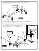
11. Attach legs (#19 & 24) to table top with Hex Bolt (#29), two Plastic Washers (#38) and Locknut (#34). Attach leg brace to Leg Mounting Bracket (#25) with Phillips Head Screw (#23) and #10-24 Locknut (#44) as shown in Detail 1. Attach leg levelers (#26) to bottom of the legs (#19 & 24) as shown in Figure 7. 26 12. Attach Net Plate (#47) as shown in Detail 1A & Detail 1B. Make sure the Nut Plate is flush with the corner of the table and make sure to use the top three holes in the nut plates.
13. Lay out Rails (#2, #3, & #4) around edges of table 5 top and add Vinyl End Caps (#45 & 46) to ends of Left and Right Side rails. See Figure 8. 14. Line up holes in rails with Indentations in table top and secure using Screws (#5). See Figure 8 & Detail F. Note: Right hand Rail (#2) has “Ping Pong” screened on it and Left hand Rail (#3) has “The Original Since 1901”. 4 4 *NOTE: Legs not .
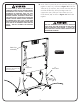
15. Line up holes in Storage Tray with Indentations in table top and attach it to the bottom of the table with four (#5) screws as shown in Figure 9 and Detail J. 16. Lay Corner Caps (#40) on table as shown in Figure 9. 7 5 Secure to bottom of table with three Screws (#5). See Detail H & Detail G. 40 NOTE: Prepare an area for the assembly of the second table top half. If necessary, move the first table top half aside with the aid of a helper.
AT LEAST TWO (2) ADULTS ARE NEEDED TO COMPLETE THE REST OF THIS ASSEMBLY! WHEN ASSEMBLING TOPS TO BASE, HANDLE TOP ASSEMBLIES BY GRASPING ONLY THE TOPS THEMSELVES. DO NOT GRASP METAL LEGS, USUPPORT, LINKAGE, OR HINGES. THESE PARTS CAN MOVE AND COULD PINCH FINGERS OR HANDS CAUSING SERIOUS INJURY! ASSEMBLE AS SHOWN WITH LEGS FULLY CLOSED AND TOPS IN A VERTICAL POSITION. DO NOT OPEN LEGS AND TRY TO ASSEMBLE. TABLE TOPS ARE HEAVY - DO NO T ATTEMPT TO ASSEMBLE ALONE! 18.
19. Secure U-support tube (#21) to Strut Tubes (#17) with two Screws (#5) as shown in Figure 11. Align holes in U-support with holes in Strut Tubes and thread screw (#5) into hole in Strut Tube (#17). Tighten screws all the way but be careful not to over tighten as you could strip threads on screws. DO NOT OPEN THE TABLE TO PLAYING POSITION UNTIL BOTH TOPS ARE INSTALLED! DO NOT LEAVE TABLE STANDING UNATTENDED. IT COULD BE KNOCKED OVER CAUSING SERIOUS BODILY INJURY OR PROPERTY DAMAGE. 20.
DO NOT OPEN THE TABLE TO PLAYING POSITION UNTIL BOTH TOPS ARE INSTALLED! DO NOT LEAVE TABLE STANDING UNATTENDED. IT COULD BE KNOCKED OVER CAUSING SERIOUS BODILY INJURY OR PROPERTY DAMAGE. If you want to see a video on how to position hinge (#18) go to: http://www.escaladesports.com/customer-service/videos.html Or Scan with your smartphone: Note: If hinge (#18) is positioned as shown in Detail M, you will have to rotate the hinge to the position shown in Detail N.
OPENING AND CLOSING INSTRUCTIONS CAUTION: EXERCISE CAUTION IN OPENING/CLOSING TABLE. SMALL CHILDREN, OR CHILDREN NOT PROPERLY INSTRUCTED IN ITS USE, MUST NOT BE ALLOWED TO OPEN/CLOSE TABLE. IMPROPER HANDLING AND MISUSE CAN RESULT IN SERIOUS INJURY OR DAMAGE. DO NOT CLIMB, STAND, OR JUMP ON TABLE. MOISTURE AND CONDENSATION WILL DAMAGE PLAYING SURFACE OF THIS TABLE. STORE IN DRY, INDOOR PLACE. TO OPEN: 1. Hold center of top edge. Gently pull outward to midway position. ....
by firmly gripping the vertical net post within height adjustment slot 3. Storage Caution: To prevent damage to the net system and/or table top, the post assembly must be pivoted toward side of table before lifting table tops to storage position. Loosen knob and pivot net post toward table side as far as it will go. Retighten Knob.
ONE YEAR LIMITED WARRANTY This consumer warranty extends to the original consumer purchase of any ESCALADE® SPORTS Product (hereinafter referred as the "Product"). WARRANTY DURATION: This Product is warranted to the original consumer purchase of a period of one (1) year from the original purchase.
4 7 40 4 3 1 34 38 5 44 2 25 23 29 19 24 24 22 21 20 29 34 35 6 38 37 5 5 26 30 45 5 18 34 47 46 31 8 17 15 16 39 36 11 10 28 14 32 8 43 28 13 27 9 12 Replacement Parts List for Model Number T8674 Key# 1 2 3 4 5 6 7 8 9 10 11 12 13 14 15 16 17 18 19 20 21 22 23 Part # 4A-5536-00 2S-6869-22 2S-6869-23 2S-4670-13 1B-4082-99 3M-6273-00 3M-4166-02 8S-6841-11 2Q-6459-01 2Q-6460-01 2B-4043-00 3M-6884-00 1B-6195-00 3M-6274-00 2W-5045-02 8S-6842-04 8S-6856-05 4A-5423-02 1A-4132
MESA DE TENIS NÚMERO DE MODELO T8674 MANUAL DEL USUARIO 1. Lea este manual cuidadosamente antes de empezar a ensamblar. Lea completamente cada uno de los pasos antes de empezar cada paso. 2. Algunas partes pequeñas pueden ser empacadas dentro de las partes grandes. Verifique en el interior de todas las partes y cartones antes de ensamblar o solicitar partes. 3.
IDENTIFICADOR DE TORNILLOS 34 27 29 3/8-16 Tuerca de Seguridad (Cant. 12) 30 1/4-20 X 2 3/4 Tornillo de Cabeza Hexagonal (Cant. 8) 1/4-20 X 1 1/2 Tornillo Phillips (Cant. 4) 32 31 1/4-20 X 3 1/4 Tornillo de Carruaje (Cant. 4) 1/4-20 Tuerca de Mariposa (Cant. 4) 37 35 36 #8-32 X 1 1/4 Tornillo para lamina de metal (Cant. 4) Separador de 3/4” (Cant. 4) #10-24 X 1/2 Tornillo Phillips (Cant. 4) 1/4-20 Tuerca de Seguridad (Cant. 12) 3/8-16 x 3 1/2 Tornillo de Cabeza Hexagonal (Cant.
1A. Adjunte las llantas (#9 y #10) a el Carril. Deslice una llanta con seguro (#10) a través de Carril (#8) y asegurela con una Contratuerca (#11) como se muestra en la Figura 1. Golpe la Contratuerca (#11) ligeramente con un martillo para asegurarla en su lugar. En el otro extremo del carril adjunte una llanta sin seguro (#9). Asegúrese que cada carril tenga una llanta con seguro y una llanta sin seguro. Repita el paso para el segundo Carril.
3. Una la Tabla Inferior (#15) a el Carril con Llantas (#8) como esta mostrado en la Figura 3. Voltee los Carriles como están ilustrados y una la Tabla Inferior con los cuatro Tornillos de Carruaje (#31) y las cuatro Tuercas de Mariposa (#32). Atornille tuercas asegurándose que estén apretadas y seguras. Nota: La placa de Soporte (#43) debe de estar en el lado de adentro del carril con llantas (#8) como está mostrado. 31 43 8 15 31 8 32 Figura 3 32 4.
5. Coloque el Tablero (#1) sobre una superficie lisa y plana con el lado pintado hacia abajo. Use la caja para proteger la pintura de la superficie del tablero. ADVERTENCIA: CUANDO ENSAMBLE LA MESA, ES EXTREMADAMENTE IMPORTANTE QUE TODAS LAS ABRAZADERAS EN “U” (#22) ESTÉN PUESTAS COMO ESTÁN MOSTRADAS EN LA FIGURA DE ABAJO. SI LAS ABRAZADERAS EN “U” ESTÁN COLOCADAS INCORRECTAMENTE, USTED LE OCASIONARA DAÑOS IRREPARABLES A SU MESA CUANDO TRATE DE ABRIRLA EN LA POSICIÓN DE JUEGO. 6. 6.
ADVERTENCIA: NO USE UN TALADRO ELECTRICO PARA COLOCAR LA BISAGRA (#18) PODRÍA BARRER EL TORNILLO EN LA MADERA Y PUEDE CAUSAR DAÑOS IRREPARABLE A LA MESA. NO APRIETE DEMASIADO LOS TORNILLOS POR QUE PUEDEN DAÑAR LA MADERA! 10. Ensamble las partes a la base del tablero con los Tornillos (#5) como se muestra en la Figura 6, Detalle C y Detalle D. 5 5 20 a) Alinee los orificios del Soporte de Montaje (#20) y (#25) con los orificios del tablero y sujetelo con los Tornillos (#5).
11. Instale las patas (#19 & 24) al tablero de la mesa con los Tornillos Hexagonales (#29), dos Rondanas de Plástico (#38) y la Tuerca de Seguridad (#34). Sujete la abrazadera de la pata al soporte (#25) con los Tornillo Phillips (#23) y Tuerca de Seguridad #10-24 (#44) como está mostrado en el Detalle 1. Inserte los Tapones de las patas (#26) a las Patas como esta mostrado en la Figura 7. 26 12. Ponga la Placa con Tuerca (#47) como se muestra en el Detalle 1A y 1B.
11. Coloque los Rieles (#2, #3, #4) en los bordes del tablero y coloque las Tapas del Riel (#45 y #46) en los extremos de los rieles (#2 y #3). Vea la Figura 8. 5 13. Alinee los orificios de los rieles con los orificios de guía de la base del tablero y asegurelos utilizando los Tornillos (#5). Ver la Figura 8 y el Detalle F. Nota: Riel de mano derecha (#2) dice “Ping Pong” y el Riel de mano izquierda (#3) dice “The Original Since 1901”.
15. Alinee los orificios de la charola con los orificios de guía del tablero, atornillela con cuatro tornillos (#5). Vea la Figura 9 y Detalle J. 16. Coloque los Protectores de Esquinas (#40) a la mesa usando un 7 5 tornillo (#5) como se muestra en el Detalle H y Detalle G. 40 NOTA: Prepare una área para el ensamblado de la Segunda mitad de la mesa. Si es necesario mueva el primer tablero a un lado con la ayuda de otra persona. Asegúrese de ponerlo en una lugar donde no estorbe y no se dañe.
ADVERTENCIA! POR LO MENOS SE REQUIEREN DOS (2) ADULTOS PARA TERMINAR EL RESTO DEL ENSAMBLADO! CUANDO ENSAMBLE LOS TABLEROS A LA BASE, MUEVA EL TABLERO SOSTENIENDOLO ÚNICAMENTE DE LA PARTE POSTERIOR, NO SE DETENGA DE LAS PATAS DE METAL, DEL TUBO DE SOPORTE-U, DE LOS TUBOS CONECTORES Ó DE LAS BISAGRAS. ESTAS PARTES PUEDEN MOVERSE Y PODRÍAN LASTIMAR LOS DEDOS O LAS MANOS, CAUSANDO LESIONES GRAVES.
19. Atornille el Tubo del Soporte-U (#21) a los Tubos Estructurales (#17) con los dos Tornillos (#5) como se muestra en Figura 11. Alinee los orificios ADVERTENCIA! ! de los tubos de Soporte-U con los Tubos Estructurales e inserte los Tornillos (#5) en los orificios de los Tubos Estructurales (#17).
Nota: Si la bisagra (#18) esta colocada como se muestra en Detalle M, usted tendrá que girar la bisagra a la posición que se muestra en Detalle N. NO desatornille la bisagra, usted puede girar la bisagra sin desatornillarla de la mesa. Si desea ver un vídeo para ver la posición de bisagra (# 18) vaya a: http://www.escaladesports.com/customer-service/videos.html O escanear con su teléfono inteligente 21. Una las Bisagras (#18) a los Tubos Estructurales (#17) como está mostrado en la Figura 12y Detalle B.
INSTRUCCIONES PARA ABRIR Y CERRAR ADVERTENCIA! PONGA ATENCIÓN AL ABRIR Y AL CERRAR LA MESA. MENORES DE EDAD QUE NO SABEN EL USO APROPIADO DE LAS INSTRUCCIONES NO SE LES DEBE PERMITIR ABRIR Y CERRAR LA MESA. EL MANEJO O USO INCORRECTO DE LA MESA PUEDE CAUSAR LESIONES GRAVES O DAÑOS MATERIALES. NO DEBEN DE PARARSE, SUBIRSE O BRINCAR SOBRE LA MESA. LA HUMEDAD Y LA CONDENSACIÓN DAÑARÍAN LA SUPERFICIE DE LA MESA. LA MESA DEBE ESTAR EN EL INTERIOR Y EN UN LUGAR SECO. PARA ABRIR: 1. 2. 3.
2. Ajustes A - Ajuste la tensión general de la red aflojando levemente la manija y moviendo el soporte. Ajuste suavemente la manija. El soporte deberá estar en escuadra con la mesa cuando haya llegado al tope. (Ver Descripción del sistema de red) DESCRIPCION DEL SISTEMA DE RED B - Ajuste la tensión de la cuerda con la cadena de cuentas a cada lado. Asegúrese de que la cadena esté ajustada en el gancho.
GARANTÍA LIMITADA POR UN AÑO Esta garantía es aplicable para consumidores de la compra original de cualquier producto ESCALADE® SPORTS (en adelante denominado el "Producto"). DURACIÓN DE LA GARANTÍA: Se garantiza este Producto al comprador original por un período de un (1) año a partir de la fecha de compra.
4 7 40 4 3 1 34 38 5 44 2 25 23 29 19 24 24 22 21 20 29 34 35 6 38 37 5 5 26 30 45 5 18 34 47 31 46 8 17 15 16 39 36 11 10 28 14 32 8 43 28 13 27 9 12 Lista de partes reemplazables para el modelo T8674 Key# 1 2 3 4 5 6 7 8 9 10 11 12 13 14 15 16 17 18 19 20 21 22 23 Part # 4A-5536-00 2S-6869-22 2S-6869-23 2S-4670-13 1B-4082-99 3M-6273-00 3M-4166-02 8S-6841-11 2Q-6459-01 2Q-6460-01 2B-4043-00 3M-6884-00 1B-6195-00 3M-6274-00 2W-5045-02 8S-6842-04 8S-6856-05 4A-5423-02 1A-