
Instructions / Assembly
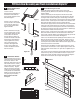

NOTE:
It is very important to determine whether you will be installing
a Mounting Board prior to installing the track. If you do need to
install a Mounting Board, it MUST be installed rst.
(Mounting Board Not Included)
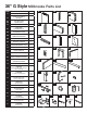
PVC Barn Door Assembly and Track Installation G Style 36”
Please read ALL instructions before you begin installation.
You MUST determine if you need a Mounting Board prior to doing ANY installation. Due to many overlapping factors
such as the location of wall studs, the weight of a Barn door and the various types of trim used in homes, we
recommend using a Mounting Board in all situations. Track must be installed into Solid Blocking or Head Casing.
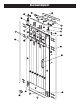
Fig. 6
Fig. 7
1-1/2”
4-1/2”
2”
2”
17.75
INCH
17.75
INCH
17.75
INCH
17.75
INCH
4.75
INCH
H +
3
INCH
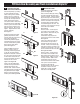
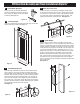
2. Determine Track
Location
On the same side where you made
your Height mark, measure 4-3/4”
over from the door jamb and draw
a line so the 2 measurements
intersect. This will be the location
of the rst hole in the Track.
See Figure 1.
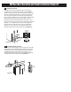
3. Insert Mounting Hardware
Drill pilot hole. Insert lag bolt (X) through the rst track hole,
then place the track spacer (S) through the bolt on back of the
track. Install the lag bolt with ½” socket ratchet. Do not tighten
fully. Swing the track up and use the level to ensure the track is
straight. Mark the remaining holes in the track. Drill remaining
pilot holes. Slide the stopper (T) onto the track for the end of
the track where you installed the rst bolt so it is between the
rst and second holes on that end of the track. Install the next
bolt and spacer at this end of the track. Install the remaining
bolts and spacers. Go back and fully tighten the rst bolt. Slide
the remaining stopper onto the other end of the track. Do not
set either stopper at this point. Refer to Figures 2A, 2B & 2C.
Figure 1
NOTE NOTE
1. Measure for Track Height
In order to determine the proper Height for your Barn Door
Track, add 3” to the height of the door being installed. Locate
and mark this height on the wall (or mounting board) on the
side of the door jamb where the door would be in the closed
position. See Figure 1.
Fig. 2A
Fig. 2B
Fig. 2C
Figure 2A
Masonry Application
Figure 2B
Mounting Board/Stud Application
Fig. 2A
Fig. 2B
Fig. 2C
Fig. 2A
Fig. 2B
Fig. 2C
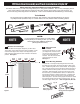
Tools Needed
You will need a Pencil, Phillips head screwdriver, Tape measure, Drill, Assorted Drill bits (5/16” & 3/8”),
6” phillips head bit (included in kit), 1/2” socket ratchet, 4ft Level, Rubber mallet and Safety glasses.