DTC25U TRANSCODER INSTRUCTION MANUAL PINEAPPLE TECHNOLOGY, INC
PINEAPPLE TECHNOLOGY, INC. DTC25U Operating and Service Manual TABLE OF CONTENTS Section l --- SAFETY NOTICES ………………………………………………………………………… 2 ** READ THIS SECTION BEFORE INSTALLATON ** Secton ll --- TRANSCODER SPECIFICATIONS …………………...………………………………… 3 Section lll --- TRANSCODER INSTALLATION ……………………………………………………… 4 Section lV --- TRANSCODER TURN-ON ……………………………………………………………… 5 Section V --- THEORY OF OPERATION A. Introduction ……………………………………………………………………………… B.
Section I Safety Notices
PINEAPPLE TECHNOLOGY, INC. DTC25U Operating and Service Manual l --- SAFETY NOTICES l ---SAFETY NOTICES ** READ THIS SECTION BEFORE INSTALLATION ** SEVERE ELECTRICAL SHOCK OR BURNS MAY OCCUR IF THIS EQUIPMENT IS USED IMPROPERLY. NEVER WORK ON THIS EQUIPMENT ALONE. ALWAYS HAVE ANOTHER PERSON PRESENT WHILE WORKING ON ELECTRICAL CIRCUITS OR MOVING EQUIPMENT. COMMUNICATIONS TO EMERGENCY SERVICES SHOULD BE AVAILABLE AT ALL TIMES.
Section II Transmitter Specifications
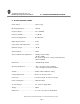
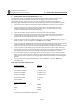
PINEAPPLE TECHNOLOGY, INC. DTC25U Operating and Service Manual II – TRANSCODER SPECIFICATIONS II – DTC25U SPECIFICATIONS Power Output ………………………… 25W Average RF Output Impedance………………… 50 ohms Frequency Range……………………… 470 – 806 MHz Frequency Stability…………………… ± 1,000 Hz Error Vector Magnitude………………. 4% Maximum Digital Signal to Noise……………….. 27 dB Group Delay with Output Filter………. ± 25 ns Harmonic Output………………............ -50 dB Spurious Output………………………. -50 dB Spectrical Mask with Output Filter…...
Section III Transmitter Installation
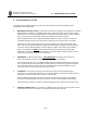
PINEAPPLE TECHNOLOGY, INC. DTC25U Operating and Service Manual lll -- TRANSCODER INSTALLATION lll -- TRANSCODER INSTALLATION To ensure long and reliable trouble-free service from the DTC25U transcoder the following steps for installation are recommended: 1. MECHANICAL INSTALLATION: The DTC25U Transcoder was designed to be installed in a building protected from the weather. The building should have a hard-surface floor such as concrete with a moisture barrier.
Section IV Transmitter Turn-On
PINEAPPLE TECHNOLOGY, INC. DTC25U Operating and Service Manual lV -- TRANSCODER TURN-ON PROCEDURE lV --- TRANSCODER TURN-ON PROCEDURE (Page 1 of 3) See the previous section on installation before proceeding with this section. Improper installation of the transcoder can cause serious damage to the equipment or operating personnel and may void manufacturers warranty. Initial turn on and check out is very important for the broadcast engineer to learn how to setup and operate the transcoder.
PINEAPPLE TECHNOLOGY, INC. DTC25U Operating and Service Manual lV -- TRANSCODER TURN-ON PROCEDURE lV --- TRANSCODER TURN-ON PROCEDURE (Page 2 of 3) Note: Allow the DTC25U to warm up for at least one (1) hour before making the final adjustment. If transmitter is not warmed up, the output power will require re-adjustment to proper level when it is warm. 10. Select the FWD Power setting on the rotary switch associated with the front panel meter on the LTX Mainframe assembly.
PINEAPPLE TECHNOLOGY, INC. DTC25U Operating and Service Manual lV -- TRANSCODER TURN-ON PROCEDURE lV --- TRANSCODER TURN-ON PROCEDURE (Page 3 of 3) 11. The receive signal antenna can now be connected to the input of the transcoder as required. Note: The receive antenna should be located so that it will not pick up the transmitter output signal. Even when the input and output channel separation may seem to be considerable, the input receiver front end can be over loaded.
Section V Theory of Operation
PINEAPPLE TECHNOLOGY, INC. UTX1K ULTRA Operating and Service Manual V -- THEORY OF OPERATION V --- THEORY OF OPERATION (Page 1 of 2) A. INTRODUCTION The DTC25U transcoder was designed to meet or exceed all FCC applicable specifications for TV broadcast equipment. Special attention was given to the selection of sub-assemblies and components to achieve maximum reliability and minimum down time. The construction of the DTC25U is BASIC and MODULAR with most components field replaceable.
PINEAPPLE TECHNOLOGY, INC. DTC25U Operating and Service Manual V -- THEORY OF OPERATION V. THEORY OF OPERATION (CONTINUED) (Page 2 of 2) C. LTX Mainframe Power Amplifier Cabinet - The cabinet is constructed of heavy gauge steel and is very durable. This enclosure is painted black and is resistive to harsh environment. Standard 19 inch rack mounting. LTX-D1 Mainframe Assembly - Internal sub-assemblies include the following: 1. DC Power Supply 2. RF Deck 3. Status Monitoring (1A0035) 4.
Section VI Schematic and Parts List
PINEAPPLE TECHNOLOGY, INC. DTC25U Operating and Service Manual A.
AC Inlet Ant RF In Larcan 8VSB Regen Transcoder DC Out IF XC100LC RF Input DC Inlet Drake DCU860 Up Conv AC Inlet RF Input RF Output Mon LTX-D1 Mainframe Assembly RF Probe DB9 Page 11 Remote Interface SIZE 1:1 FSCM NO. A SCALE SHEET DTC25U DigitalDWGTranscoder NO. Pineapple Technology, Inc.
PINEAPPLE TECHNOLOGY, INC. DTC25U Operating and Service Manual B.
Page 13 FWD Pwr P1 P2 P3 Gnd P4 Shutdown P5 P6 RFLD Pwr P7 ALC P8 +8 VDC P9 110 VAC RF DB9 PA Fan 110VAC ON\OFF SW +DC RF IN M 110 VAC AC Inlet PS1 Power Supply 27VDC 11A DVR10U DC Output From RF Output Monitor Tap +DC RF IN M U250LD RF Deck DC Metering and DC Monitoring 1A0300 LTX-D1 Mainframe SCALE 1:1 FSCM NO. DWG NO. SHEET 1 REV B LTX-D1 Mainframe Assembly A SIZE RF RF Probe Pineapple Technology, Inc.
SECTION VI - SCHEMATIC AND PARTS LISTS SUB-SECTION C - DTC25U No Serviceable Parts Pineapple Technology, Inc. Rocklin, CA BPUD100 Stringent Mask Filter SIZE Page 14 SCALE FSCM NO. DWG NO.
SECTION VI - SCHEMATIC AND PARTS LISTS SUB-SECTION D - DTC25U Used as required No Serviceable Parts Pineapple Technology, Inc. Rocklin, CA SIZE Page 15 SCALE Low Pass Filter CIRCUIT DIAGRAM FSCM NO. DWG NO.
Section VII Recommended Routine Maintenance
PINEAPPLE TECHNOLOGY, INC. DTC25U Operating and Service Manual VII -- ROUTINE MAINTENANCE VII --- ROUTINE MAINTENANCE Routine Maintenance on the transmitter is very simple and straight forward. PTI recommends the following steps to ensure long and eliable trouble-free service. SCHEDULE: DAILY OR WEEKLY SERVICE 1. Check output power level to ensure that the meter is reading in the GREEN. If the level has changed adjust the output level to 100% using the modulator output level adjust. 2.
Section VIII Adjustments and Tuning
PINEAPPLE TECHNOLOGY, INC. DTU25C Operating and Service Manual VIII -- ADJUSTMENTS AND TUNING VIII --- ADJUSTMENTS AND TUNING The DTU25C is a new series of digital transcoders offered by Pineapple Technology, Inc. The latest in LDMOS device and circuit technology are employed to ensure reliable and serviceable operation for many years. There are very few adjustments necessary to maintain full service condition.
Section IX Problem Solving & Troubleshooting
PINEAPPLE TECHNOLOGY, INC. DTC25U Operating and Service Manual IX -- PROBLEM SOLVING/TROUBLE SHOOTING IX - PROBLEM SOLVING & TROUBLE SHOOTING (Page 1of 2) The DTC25U is a "MODULAR ASSEMBLY" where most of the sub-assemblies can be removed and or replaced as necessary as necessary to maintain full service. To service this transmitter, it is best to become familiar with the various sub-assemblies by reviewing the transmitter block diagram and it's associated subs shown in the introduction.
PINEAPPLE TECHNOLOGY, INC. DTC25U Operating and Service Manual IX -- PROBLEM SOLVING/TROUBLE SHOOTING IX - PROBLEM SOLVING & TROUBLE SHOOTING (Page 2of 2) TEMP FAULT RED indicates over temperature of PA or High VSWR If High VSWR, the light will cycle 10 seconds OFF and 2 seconds ON Put transmitter in STANDBY. Investigate antenna installation and connections, check transmission lines and connections. Check that transcoder up converter is on frequency.
Section X Warranty
PINEAPPLE TECHNOLOGY, INC. UTX1K ULTRA Operating and Service Manual X -- WARRANTY X -- WARRANTY The WARRANTY provided by Pineapple Technology, Inc. (PTI) on this transmitter is detailed below. It should be noted that some of the equipment sub-systems have warranty coverage by the orginal manufacture that differs from the standard warranty provided by PTI Warrantydetails on equipment falling into this category may be found in the Manufacturers instruction manual provided with the transmitter.