
User's Guide

is located) in place using the short screws in the front left and right corners. Then
proceed to pop in the bottom panel into place. Secure the bottom section (where hinges
are located) by screwing in the left and right corners. Then screw in the remaining screws
and run your finger though the rim on the chassis to make sure its fitted correctly. Note
that the front uses the remaining 2 short screws.
NOTE: The screws are small and should only be finger tight. Too much force will strip the
threads. If after installing screws the back cover plate has not seated properly on one
side, open the display and hold the base on either side of the keyboard and gently flex
the base with both hands in opposing directions. Once the side pops further in, then
recheck the screws on that side. If it does not pop back in, just let it be.
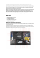
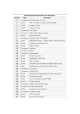
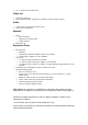
Main chips
•
RK3399 system-on-chip (1)
•
LPDDR4 SDRAM (21)
•
SPI NOR flash memory (29)
•
eMMC flash memory (26)
•
WiFi/BT module (27)
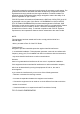
Mainboard Switches and Buttons
There are two switches on the main board: disabling the eMMC (24), and enabling UART
(9) via headphone jack.
The Reset and Recovery buttons (28): the reset button performs an immediate reset of
the laptop. The Recovery button is used to place the device in maskrom mode; this mode
allows flashing eMMC using Rockchip tools (e.g. rkflashtools)