
Instruction Manual


- 5 -
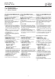
Anschlüsse Connections Raccordements
Stiftstecker 5-pol. M12 (male) Connector 5 pin M12 (male) Connecteur mâle M12 à 5 broches
Anschlussbelegung Terminal assignment Repérage des broches
Anschlussbezeichnung im
Blockschaltbild/
Terminal designation/
Désignation des bornes
Funktion/
Function/
Foncion
PIN/
Broche
Adernfarbe (Pilz Kabel)/
Cable colour (Cable Pilz)/
Couleur du fil (fil de Pilz)
1 Eingang Kanal 1/
Input, channel 1/
Canal d'entrée 1
1 braun/brown/marron
2 Ausgang Kanal 1/
Output, channel 1/
Canal de sortie 1
2 weiß/white/blanc
30 V UB3blau/blue/bleu
4 Eingang Kanal 2/
Input, channel 2/
Canal d'entrée 2
4 schwarz/black/noir
5 Ausgang Kanal 2/
Output, channel 2/
Canal de sortie 2
5 grau/grey/gris
WICHTIG
Der Hilfskontakt mit LED
darf mit PNOZ X-Geräten nur mit Versor-
gungsspannung bis 24 V DC betrieben
werden
ist mit PNOZ X-, PNOZelog- und
PNOZmulti-Geräten nicht in Reihe
schaltbar
NOTICE
The auxiliary contact with LED
May only be operated with a supply volt-
age of up to 24 VDC with PNOZ X units
May not be connected in series with
PNOZ X, PNOZelog and PNOZmulti
units
IMPORTANT
Le contact d'information avec LED
ne doit être utilisé, pour les appareils
PNOZ X, qu'avec une alimentation jus-
qu'à 24 V DC
ne peut pas être monté en série avec les
appareils PNOZ X, PNOZelog et
PNOZmulti
Anschluss an Auswertegeräte Connection to evaluation devices Raccordement aux appareils de contrôle
785477899
Der Hilfskontakt mit LED kann als Meldeaus-
gang verwendet werden (siehe technische Da-
ten)
1104750091
Bitte beachten Sie:
das Netzteil muss den Vorschriften für Klein-
spannungen mit sicherer Trennung (SELV,
PELV) entsprechen.
die Ein- und Ausgänge des Sicherheitsschal-
ters müssen eine sichere Trennung zu Span-
nungen über 60 V AC besitzen.
The auxiliary contact with LED may be used as
a signal output (see Technical details)
Please note:
The power supply must meet the regulations
for extra low voltages with safe separation
(SELV, PELV).
the inputs and outputs of the safety switch
must have a safe separation to voltages over
60 V AC.
Le contact d'information avec LED peut être
utilisé comme sortie d'information (voir les ca-
ractéristiques techniques)
Tenez compte de ce qui suit :
Cette alimentation doit être conforme aux
prescriptions relatives aux basses tensions à
séparation galvanique (SELV, PELV).
Les entrées et les sorties du capteur de sé-
curité doivent posséder une séparation gal-
vanique pour les tensions supérieures à
60 V AC.
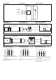
Anschluss an PNOZ, PNOZ X, PNOZpower,
PNOZsigma, PNOZelog
Connection to PNOZ, PNOZ X, PNOZpower,
PNOZsigma, PNOZelog
Raccordement aux PNOZ, PNOZ X,
PNOZpower, PNOZsigma, PNOZelog
1
2
3
5
4
PNOZ p1p
PNOZ p1vp
PNOZ X2/X2P
PNOZ X2.1
(nur 24 V DC/
24 V DC only/
24 V DC seulement)
PNOZ X2.3P
PNOZ X2.7P
PNOZ X2.8P
PNOZ X2C
PNOZ X2.1C
(nur 24 V DC/
24 V DC only/
24 V DC seulement)
PNOZ X4/X8P
PNOZ X9
PNOZ X10/X10.1
PNOZ X10.11
PNOZ Ex
PNOZ e1p
PNOZ e1.1p
PNOZ e1vp
PNOZ e6.1p
PNOZ e6vp
PNOZ s3
PNOZ s4
PNOZ s5
S22
S21
S11
S12
3
1
2
4
5
A1
A2
24 V
0 V
PSENma
PNOZ
PNOZ X2.9P
S12
S52
S11
S11
3
1
4
2
5
A1
A2
24 V
0 V
PSENma
PNOZ