
Manual

PNOZ s9
Operating Manual PNOZ s9
21401-EN-08
8
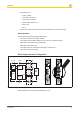
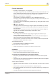
} 2-channel input circuit
Base unit: Safety relays
PNOZ s3, PNOZ s4, PNOZ
s5
Base unit: Safety relays
PNOZ s1, PNOZ s2
The input circuit is connected
and evaluated via the con-
nector.
Interface
PNOZsigma
PNOZ s1
PNOZ s2
PNOZ s9
A1
24 V DC
S34
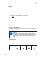
Base unit: Two-hand control
device PNOZ s6
Base unit: Two-hand control
device PNOZ s6.1
The input circuit is connected
and evaluated via the con-
nector.
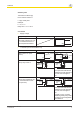
} Application
Without feedback loop With feedback loop
Without base unit
Legend
} S3: Start button
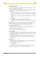
Operation
The unit is ready for operation when the Power LED is permanently lit.
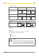
LEDs indicate the status and errors during operation:
LED on
LED flashes
Information
Status indicators and error indicators may occur independently. In the case
of an error display, the "Fault" LED will light or flash (exception: "Supply
voltage too low"). An LED that is also flashing indicates the potential cause
of the error. An LED that is lit and is static indicates a normal operating sta-
tus. Several status indicators and error indicators may occur simultaneously.