
Manual


PNOZ s9
Operating Manual PNOZ s9
21401-EN-08
7
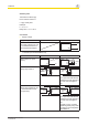
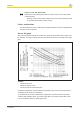
Set delay time
Time selector switch "t[s]"
Factor selector switch "n"
n x t[s] = Delay time
Example:
t = 4 s, n = 5
Delay time = 5 x 4 = 20 s
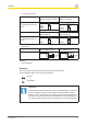
Connection
} Supply voltage
Supply voltage AC DC
Caution!
The supply voltage may only
be connected as shown in
the examples listed below.
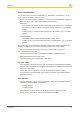
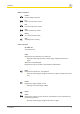
} 1-channel input circuit/feedback loop
Input circuit Input circuit Feedback loop
Without base unit (stan-
dalone)
Base unit:
Safety relay PNOZ X
24 V DC
0 V
A2
PNOZs9
45
46
PNOZ X
S34
feedback
loop
The inputs that evaluate the
feedback loop will depend on
the base unit and applica-
tion.
Base unit:
Safety relay PNOZelog; driv-
en via semiconductor out-
puts (24 VDC)
24 V DC
0 V
A2
PNOZs9
45
46
PNOZelog
S34
feedback
loop
The inputs that evaluate the
feedback loop will depend on
the base unit and applica-
tion.
* PNOZ e1p only; all other
PNOZelog safety relays with-
out delay-on de-energisation
with PNOZ s9