PNOZ s9 Safety relays Operating Manual-21401-EN-08
Preface This document is the original document. All rights to this documentation are reserved by Pilz GmbH & Co. KG. Copies may be made for internal purposes. Suggestions and comments for improving this documentation will be gratefully received. Pilz®, PIT®, PMI®, PNOZ®, Primo®, PSEN®, PSS®, PVIS®, SafetyBUS p®, SafetyEYE®, SafetyNET p®, the spirit of safety® are registered and protected trademarks of Pilz GmbH & Co. KG in some countries.
PNOZ s9 Safety relay PNOZ s9 The unit meets the requirements of EN 60947-5-1, EN 60204-1 and VDE0113-1. In conjunction with a base unit the unit is used as a } Contact expansion module to increase the number of contacts available on a base unit. Base units are all safety relays with feedback loop monitoring.
PNOZ s9 } } LED indicator for: – Supply voltage – Input status, channel 1 – Input status, channel 2 – Switch status channel 1/2 – Start circuit – Error Plug-in connection terminals (either spring-loaded terminal or screw terminal) Safety features The unit meets the following safety requirements: } The unit monitors its own output contacts. } The safety function remains effective in the case of a component failure. } Earth fault in the feedback loop is detected.
PNOZ s9 Function description } Delay-on de-energisation, not retriggerable If the supply voltage at the input circuit is interrupted, the safety contacts will open once the set release time has elapsed, even if the safety function is cancelled during the delay time. The unit cannot be reactivated until the delay time has elapsed.
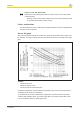
PNOZ s9 Wiring Please note: } Information given in the "Technical details" must be followed. } Outputs 17-18, 27-28, 37-38 are safety contacts; output 45-46 is an auxiliary contact (e.g. for display). } Auxiliary contact 45-46 should not be used for safety circuits! } To prevent contact welding, a fuse should be connected before the output contacts (see technical details). } Calculation of the max. cable length lmax in the input circuit: Rlmax = max.
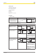
PNOZ s9 Set delay time Time selector switch "t[s]" Factor selector switch "n" n x t[s] = Delay time Example: t = 4 s, n = 5 Delay time = 5 x 4 = 20 s Connection } Supply voltage Supply voltage AC DC Caution! The supply voltage may only be connected as shown in the examples listed below.
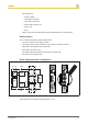
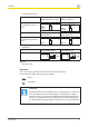
PNOZ s9 2-channel input circuit Base unit: Safety relays PNOZ s3, PNOZ s4, PNOZ s5 PNOZ s1 PNOZ s2 Base unit: Two-hand control device PNOZ s6 The input circuit is connected and evaluated via the connector. } PNOZ s9 Base unit: Two-hand control device PNOZ s6.1 A1 S34 Interface PNOZsigma 24 V DC The input circuit is connected and evaluated via the connector.
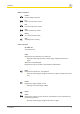
PNOZ s9 Status indicators Power Supply voltage is present. In1 Input circuit at S32 is closed. In2 Input circuit at S32 is closed. Out Safety contacts are closed. Reset 24 V DC is present at S34. Out Set delay time is running. Fault indicators All LEDs off Unit switched off. Fault Diagnostics: Plug terminator not connected } Remedy: Insert plug terminator, switch supply voltage off and then on again.
PNOZ s9 Power, In1, In2, Out, Reset, Fault Diagnostics: The operating mode selector switch "mode" is in its start position (vertical position) } Remedy: Switch off the supply voltage and set the required operating mode on operating mode selector switch "mode". Faults - malfunctions } Contact malfunctions: If the contacts have welded, reactivation will not be possible after the input circuit has opened.
PNOZ s9 Technical details General Approvals Electrical data Supply voltage Voltage Type Voltage tolerance Output of external power supply (DC) Residual ripple DC Continuous duty Max. inrush current impulse A1 Pulse duration Feedback loop Max. overall cable resistance Rlmax Single-channel at UB DC Feedback loop A1/A2 Voltage at Feedback loop DC Current at Input circuit DC Feedback loop Number of output contacts Safety contacts (N/O), delayed Auxiliary contacts (N/C), delayed Relay outputs Max.
PNOZ s9 Relay outputs 750109 Max. current 6,0 A Max. power 150 W Safety contacts, AC1 at 240 V Max. current 6,0 A Min. current 0,01 A Max. power 1500 VA Safety contacts, DC1 24 V at Max. current 6,0 A Min. current 0,01 A Max. power 150 W Utilisation category In accordance with the EN 60947-5-1 standard Auxiliary contacts, 230 V AC15 at Max. current 5,0 A Auxiliary contacts, 24 V DC13 (6 cycles/min) at Max. current 5,0 A Safety contacts, AC15 230 V at Max.
PNOZ s9 Times 750109 Switch-on delay With manual reset typ. 60 ms With manual reset max. 80 ms Delay-on de-energisation With E-STOP typ. 40 ms With E-STOP max. 50 ms Recovery time at max.
PNOZ s9 Environmental data Airgap creepage In accordance with the standard Overvoltage category Pollution degree Rated insulation voltage Rated impulse withstand voltage Protection type Mounting (e.g.
PNOZ s9 Mechanical data Dimensions Height Width Depth Weight 750109 751109 751189 98,0 mm 17,5 mm 120,0 mm 175 g 100,0 mm 17,5 mm 120,0 mm 175 g 100,0 mm 17,5 mm 120,0 mm 175 g The standards current on 2009-12 apply. Safety characteristic data Operating mode EN ISO 13849-1: 2006 PL Safety con- PL e tacts, delayed EN ISO 13849-1: 2006 Category Cat.
PNOZ s9 Order reference Order reference Product type Features Terminals Order no. 750 109 PNOZ s9 24 VDC Screw terminals PNOZ s9 C 24 VDC Spring-loaded terminals 751 109 PNOZ s9 C (coated version) 24 VDC Spring-loaded terminals 751 189 EC declaration of conformity This product/these products meet the requirements of the directive 2006/42/EC for machinery of the European Parliament and of the Council. The complete EC Declaration of Conformity is available on the Internet at www.pilz.
In many countries we are represented by our subsidiaries and sales partners. ... Please refer to our homepage for further details or contact our headquarters. Pilz GmbH & Co. KG Felix-Wankel-Straße 2 73760 Ostfildern, Germany Telephone: +49 711 3409-0 Telefax: +49 711 3409-133 E-Mail: pilz.gmbh@pilz.de Internet: www.pilz.com Technical support +49 711 3409-444 support@pilz.