
Instruction Manual

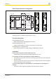
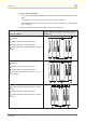
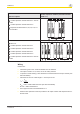
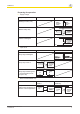
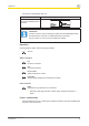
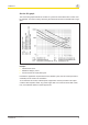
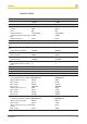
Table Of Contents
- Operating Manual PNOZ s7.1
- Preface
- Safety relay PNOZ s7.1
- For your safety
- Unit features
- Safety features
- Block diagram/terminal configuration
- Function description
- Installation
- Wiring
- Preparing for operation
- Operation
- Faults - malfunctions
- Service life graph
- Technical details
- Order reference
- EC declaration of conformity
- Contact address
PNOZ s7.1
Operating Manual PNOZ s7.1
21865-EN-08
8
} Connection to PNOZsigma base unit
Base unit: Safety relay PNOZsigma
The feedback loop is con-
nected and evaluated via the
connector.
Information
If a base unit and a contact expansion module from the PNOZsigma range
are linked via the connector, no additional wiring is necessary.
Do not connect A1 und Y1/Y2 to the expansion module!
Operation
LEDs indicate the status and errors during operation:
LED on
Status indicators
In1
Channel 1 actuated.
In2
Channel 2 actuated.
In1, In2, Out
Safety contacts are closed.
Power B1
Supply voltage applied for the expansion modules.
Fault indicators
Fault
Diagnostics: Plug terminator not connected
} Remedy: Insert plug terminator, switch supply voltage off and then on
again.
Faults - malfunctions
} Contact malfunctions: If the contacts have welded, reactivation will not be possible after
the input circuit has opened.