
Instruction Manual

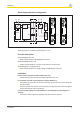
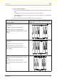
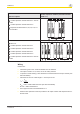
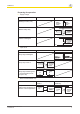
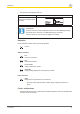
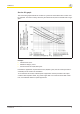
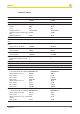
Table Of Contents
- Operating Manual PNOZ s7.1
- Preface
- Safety relay PNOZ s7.1
- For your safety
- Unit features
- Safety features
- Block diagram/terminal configuration
- Function description
- Installation
- Wiring
- Preparing for operation
- Operation
- Faults - malfunctions
- Service life graph
- Technical details
- Order reference
- EC declaration of conformity
- Contact address
PNOZ s7.1
Operating Manual PNOZ s7.1
21865-EN-08
7
Preparing for operation
} Supply voltage
Supply voltage AC DC
Base unit:
PNOZsigma safety relay
Base unit:
PNOZ X safety relay
Supply voltage for expansion
modules PNOZsigma
} Input circuit
Input circuit Single-channel Dual-channel
Base unit:
Safety relay PNOZsigma
Base unit:
Safety relay PNOZ X
Base unit:
Safety relay PNOZelog Driv-
en via semiconductor out-
puts (24 V DC)
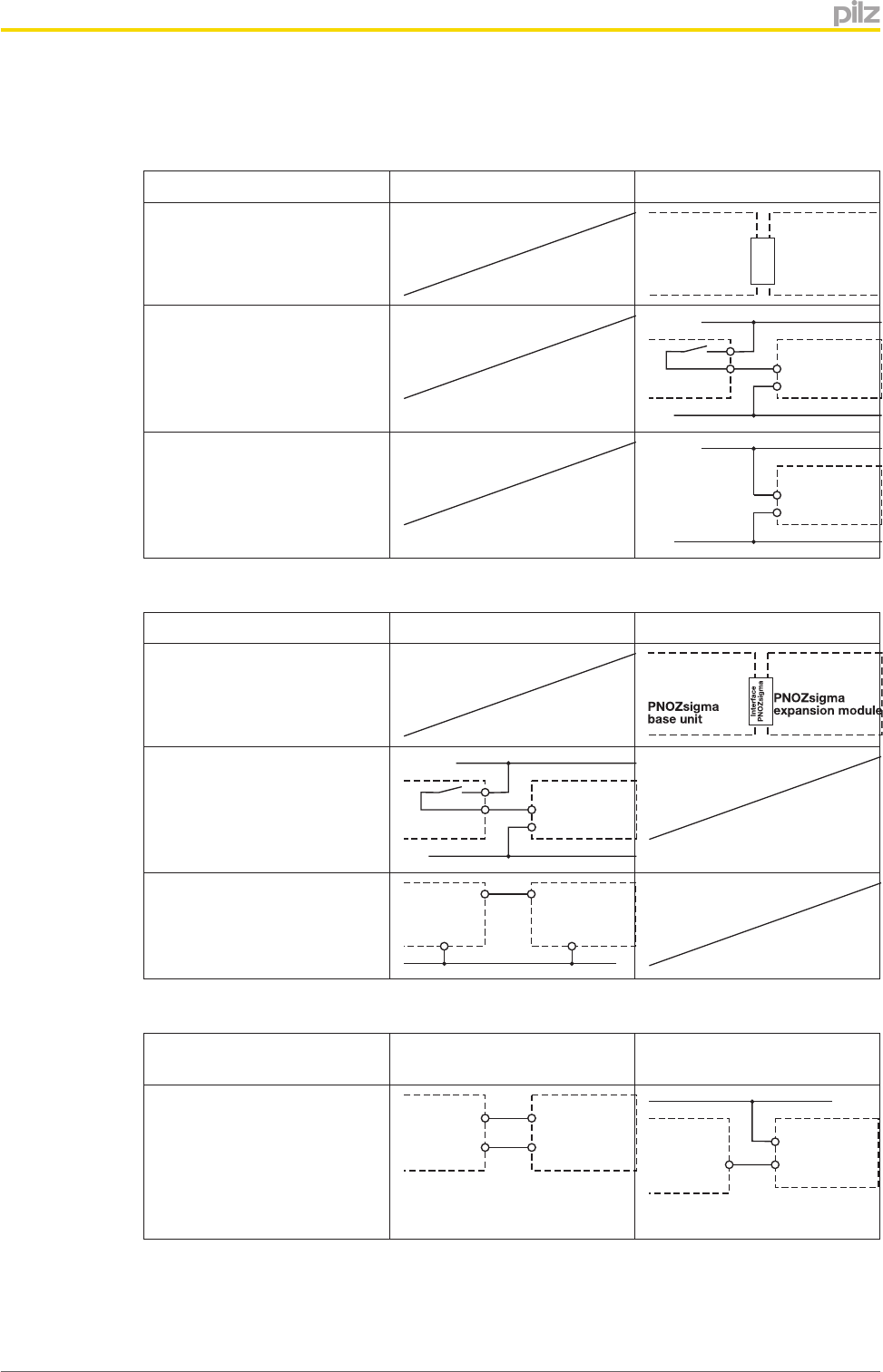
} Reset circuit/feedback loop
Reset circuit/feedback loop Base unit: Safety relay
PNOZ X
Base unit: Safety relay
PNOZelog
The inputs that evaluate the
feedback loop will depend on
the base unit and application
Y1
Y2
24 V DC
PNOZsigma
expansion
module
feedback
loop