
Instruction Manual


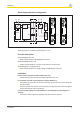
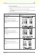
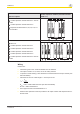
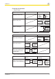
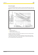
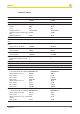
Table Of Contents
- Operating Manual PNOZ s7.1
- Preface
- Safety relay PNOZ s7.1
- For your safety
- Unit features
- Safety features
- Block diagram/terminal configuration
- Function description
- Installation
- Wiring
- Preparing for operation
- Operation
- Faults - malfunctions
- Service life graph
- Technical details
- Order reference
- EC declaration of conformity
- Contact address
PNOZ s7.1
Operating Manual PNOZ s7.1
21865-EN-08
6
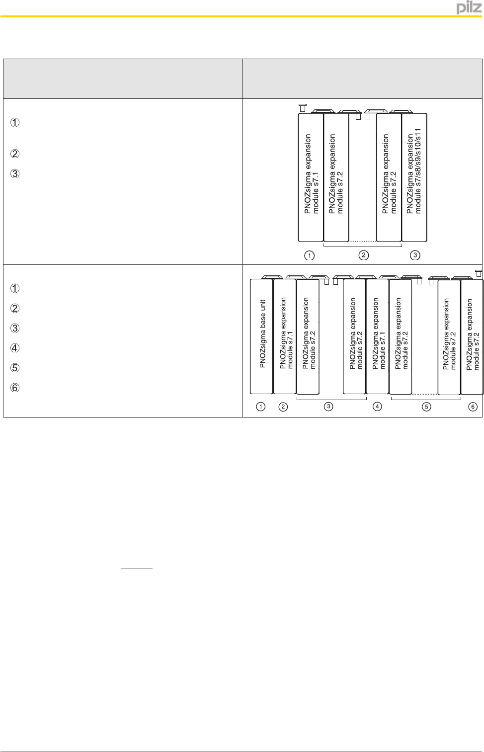
Expansion options
Please note the max. power consumption of the
contact expansion modules (see technical data
PNOZ s7.1).
: Contact expansion module PNOZ s7.1 with ter-
minator
: Contact expansion module PNOZ s7.2
: Expansion module PNOZ s7, s8, s9, s10, s11
as a terminator
: Base unit
: Contact expansion module PNOZ s7.1
: Contact expansion module PNOZ s7.2
: Contact expansion module PNOZ s7.1
: Contact expansion module PNOZ s7.2
: Contact expansion module PNOZ s7.2 with ter-
minator
Wiring
Please note:
} Information given in the "Technical details" must be followed.
} The output contacts 13-14, 23-24, 33-34 are safety contacts.
} To prevent contact welding, a fuse should be connected before the output contacts (see
technical details).
} Calculation of the max. cable length l
max
in the input circuit:
R
lmax
= max. overall cable resistance (see technical details)
R
l
/ km = cable resistance/km
} Use copper wire that can withstand 60/75 °C.
} Sufficient fuse protection must be provided on all output contacts with capacitive and in-
ductive loads.