PNOZ s7.
Preface This document is the original document. All rights to this documentation are reserved by Pilz GmbH & Co. KG. Copies may be made for internal purposes. Suggestions and comments for improving this documentation will be gratefully received. Pilz®, PIT®, PMI®, PNOZ®, Primo®, PSEN®, PSS®, PVIS®, SafetyBUS p®, SafetyEYE®, SafetyNET p®, the spirit of safety® are registered and protected trademarks of Pilz GmbH & Co. KG in some countries.
PNOZ s7.1 Safety relay PNOZ s7.1 The unit meets the requirements of EN 60947-5-1, EN 60204-1 and VDE 0113-1. The contact expansion module is used to increase the number of instantaneous safety contacts available on a base unit. Base units are all safety relays with feedback loop monitoring. The category that can be achieved in accordance with EN ISO 13849-1 depends on the category of the base unit. The contact expansion module may not exceed this.
PNOZ s7.
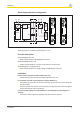
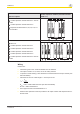
PNOZ s7.1 Control cabinet installation } The safety relay should be installed in a control cabinet with a protection type of at least IP54. } Use the notch on the rear of the unit to attach it to a DIN rail (35 mm). } When installed vertically: Secure the unit by using a fixing element (e.g. retaining bracket or end angle). Push the unit upwards or downwards before lifting it from the DIN rail. Expansion options Please note the max.
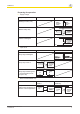
PNOZ s7.1 Please note the max. power consumption of the contact expansion modules (see technical data PNOZ s7.1). Expansion options : Contact expansion module PNOZ s7.1 with terminator : Contact expansion module PNOZ s7.2 : Expansion module PNOZ s7, s8, s9, s10, s11 as a terminator : Base unit : Contact expansion module PNOZ s7.1 : Contact expansion module PNOZ s7.2 : Contact expansion module PNOZ s7.1 : Contact expansion module PNOZ s7.2 : Contact expansion module PNOZ s7.
PNOZ s7.
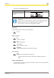
PNOZ s7.1 } Connection to PNOZsigma base unit Base unit: Safety relay PNOZsigma The feedback loop is connected and evaluated via the connector. Information If a base unit and a contact expansion module from the PNOZsigma range are linked via the connector, no additional wiring is necessary. Do not connect A1 und Y1/Y2 to the expansion module! Operation LEDs indicate the status and errors during operation: LED on Status indicators In1 Channel 1 actuated. In2 Channel 2 actuated.
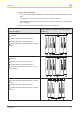
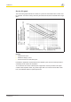
PNOZ s7.1 Service life graph The service life graphs indicate the number of cycles from which failures due to wear must be expected. The wear is mainly caused by the electrical load; the mechanical load is negligible. Example } Inductive load: 0,2 A } Utilisation category: AC15 } Contact service life: 2,000,000 cycles Provided the application requires fewer than 2,000,000 cycles, the PFH value (see technical details) can be used in the calculation.
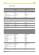
PNOZ s7.1 Technical details General Approvals Electrical data Supply voltage Voltage Type Voltage tolerance Output of external power supply (DC) Residual ripple DC Continuous duty Max. power of all expansion modules Max. overall cable resistance Rlmax Single-channel at UB DC Voltage at Input circuit DC Current at Input circuit DC Number of output contacts Instantaneous safety contacts (N/O) Inputs Number Relay outputs Max.
PNOZ s7.1 Relay outputs Contact fuse protection, external safety contacts In accordance with the standard Blow-out fuse, quick Blow-out fuse, slow Circuit breaker, 24V AC/DC, characteristic B/C Contact material Conventional thermal current while loading several contacts Ith per contact at UB DC Conv. therm. current with 1 contact Conv. therm. current with 2 contacts Conv. therm. current with 3 contacts Times Switch-on delay With automatic reset after power on typ. With automatic reset after power on max.
PNOZ s7.1 Environmental data Protection type Mounting (e.g.
PNOZ s7.1 Safety characteristic data Operating mode EN ISO 13849-1: 2006 PL Safety con- PL e tacts, instantaneous EN ISO 13849-1: 2006 Category Cat. 4 EN IEC 62061 EN IEC 62061 SIL CL PFHD [1/h] SIL CL 3 2,31E-09 IEC 61511 IEC 61511 SIL PFD SIL 3 2,03E-06 EN ISO 13849-1: 2006 TM [year] 20 All the units used within a safety function must be considered when calculating the safety characteristic data.
In many countries we are represented by our subsidiaries and sales partners. ... Please refer to our homepage for further details or contact our headquarters. Pilz GmbH & Co. KG Felix-Wankel-Straße 2 73760 Ostfildern, Germany Telephone: +49 711 3409-0 Telefax: +49 711 3409-133 E-Mail: pilz.gmbh@pilz.de Internet: www.pilz.com Technical support +49 711 3409-444 support@pilz.