PNOZ s6 Safety relays Operating Manual-21398-EN-08
Preface This document is the original document. All rights to this documentation are reserved by Pilz GmbH & Co. KG. Copies may be made for internal purposes. Suggestions and comments for improving this documentation will be gratefully received. Pilz®, PIT®, PMI®, PNOZ®, Primo®, PSEN®, PSS®, PVIS®, SafetyBUS p®, SafetyEYE®, SafetyNET p®, the spirit of safety® are registered and protected trademarks of Pilz GmbH & Co. KG in some countries.
PNOZ s6 PNOZ s6 safety relay The two-hand control relay meets the requirements of EN 574 Type IIIC. It forces the operator to keep his hands outside the danger zone area during the hazardous movement. The unit is suitable for use on controllers for metalworking presses as a component for simultaneous switching.
PNOZ s6 Safety features The two-hand control relay meets the following safety requirements: } The circuit is redundant with built-in self-monitoring } The safety function remains effective in the case of a component failure } The circuit prevents a further press stroke in the case of: } – Relay failure – Contact welding – Coil defect on a relay – Open circuit – Short circuit The unit has an electronic fuse.
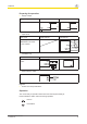
PNOZ s6 Installation Install base unit without contact expansion module: } Ensure that the plug terminator is inserted at the side of the unit. Connect base unit and PNOZsigma contact expansion module: } Remove the plug terminator at the side of the base unit and at the contact expansion module. } Connect the base unit and the contact expansion module to the supplied connector before mounting the units to the DIN rail.
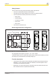
PNOZ s6 Preparing for operation } Supply voltage Supply voltage AC } DC Input circuit Input circuit Single-channel Dual-channel Two-hand pushbuttons with detection of shorts across contacts } Feedback loop Feedback loop Contacts from external contactors } Semiconductor output Legend } S1/S2: Two-hand pushbuttons Operation The unit is ready for operation when the Power LE
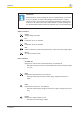
PNOZ s6 Information Status indicators and error indicators may occur independently. In the case of an error display, the "Fault" LED will light or flash (exception: "Supply voltage too low"). An LED that is also flashing indicates the potential cause of the error. An LED that is lit and is static indicates a normal operating status. Several status indicators and error indicators may occur simultaneously. Status indicators Power Supply voltage is present. In1 Pushbutton at S11 is operated.
PNOZ s6 In1, In2 alternately Fault Diagnostics: Connection error or short between S12 and S22 detected or internal error } Remedy: Rectify connection error or short across contacts, switch supply voltage off and then on again. In1 Fault Diagnostics: Simultaneity exceeded: Channel 1 too late or power-up blocked due to short-term interruption at S11; input circuits not operated simultaneously } Remedy: Open both input circuits, S12 and S22, simultaneously and then close again.
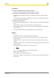
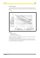
PNOZ s6 Service life graph The service life graphs indicate the number of cycles from which failures due to wear must be expected. The wear is mainly caused by the electrical load; the mechanical load is negligible. UB 24 VDC Example } Inductive load: 0,2 A } Utilisation category: AC15 } Contact service life: 2,000,000 cycles Provided the application requires fewer than 2,000,000 cycles, the PFH value (see technical details) can be used in the calculation.
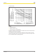
PNOZ s6 UB 48-240 VAC/DC Example } Inductive load: 0,2 A } Utilisation category: AC15 } Contact service life: 1,000,000 cycles Provided the application requires fewer than 1,000,000 cycles, the PFH value (see technical details) can be used in the calculation. To increase the service life, sufficient spark suppression must be provided on all output contacts. With capacitive loads, any power surges that occur must be noted. With contactors, use freewheel diodes for spark suppression.
PNOZ s6 Technical details General Approvals 750106 CCC, CE, GOST, KOSHA, TÜV, cULus Listed 750106 Electrical data Supply voltage Voltage 24 V Type DC Voltage tolerance -15 %/+10 % Output of external – power supply (AC) Output of external 3,5 W power supply (DC) Frequency range – AC Residual ripple 20 % DC Continuous duty 100 % Max.
PNOZ s6 Semiconductor outputs Number Voltage Current Relay outputs Max. short circuit current IK Utilisation category In accordance with the standard Auxiliary contacts, AC1 at Min. current Max. current Max. power Auxiliary contacts, DC1 at Min. current Max. current Max. power Safety contacts, AC1 at Max. current Min. current Max. power Safety contacts, DC1 at Max. current Min. current Max. power Utilisation category In accordance with the standard Auxiliary contacts, AC15 at Max.
PNOZ s6 Relay outputs Contact fuse protection, external safety contacts In accordance with the standard Blow-out fuse, quick Blow-out fuse, slow Circuit breaker, 24V AC/DC, characteristic B/C Contact fuse protection, external auxiliary contacts Blow-out fuse, quick Blow-out fuse, slow Circuit breaker, 24 V AC/DC, characteristic B/C Contact material 750106 750136 751106 751136 EN 60947-5-1 EN 60947-5-1 EN 60947-5-1 EN 60947-5-1 10 A 6A 10 A 6A 6A 4A 6A 4A 6A 4A 6A 4A 10 A 6A 10 A 6A
PNOZ s6 Times 750106 Delay-on de-energisation (reaction time in accordance with EN 574) N/O contact 30 ms N/C contact 40 ms Recovery time 250 ms Supply interruption 20 ms before de-energisation Simultaneity, chan- 0,5 s nel 1 and 2 Environmental data 750106 Climatic suitability EN 60068-2-78 Ambient temperature Temperature -10 - 55 °C range Storage temperature Temperature -40 - 85 °C range EMC EN 60947-5-1, EN 61000-6-2, EN 61000-6-4 Vibration In accordance EN 60068-2-6 with the standard Frequency 10,0 - 5
PNOZ s6 Mechanical data 750106 Cross section of external conductors with screw terminals 1 core flexible 0,25 - 2,50 mm², 24 - 12 AWG 2 core with the 0,25 - 1,00 mm², 24 same cross sec- - 16 AWG tion, flexible with crimp connectors, no plastic sleeve 0,20 - 1,50 mm², 24 2 core with the same cross sec- - 16 AWG tion, flexible without crimp connectors or with TWIN crimp connectors Torque setting with 0,50 Nm screw terminals Connection type Screw terminal Mounting type Cross section of external conductors wit
PNOZ s6 Information A safety function's SIL/PL values are not identical to the SIL/PL values of the units that are used and may be different. We recommend that you use the PAScal software tool to calculate the safety function's SIL/PL values. ATTENTION! It is essential to consider the relay's service life graphs. The relay outputs' safety-related characteristic data is only valid if the values in the service life graphs are met.
In many countries we are represented by our subsidiaries and sales partners. ... Please refer to our homepage for further details or contact our headquarters. Pilz GmbH & Co. KG Felix-Wankel-Straße 2 73760 Ostfildern, Germany Telephone: +49 711 3409-0 Telefax: +49 711 3409-133 E-Mail: pilz.gmbh@pilz.de Internet: www.pilz.com Technical support +49 711 3409-444 support@pilz.