PNOZ s6.
Preface This document is the original document. All rights to this documentation are reserved by Pilz GmbH & Co. KG. Copies may be made for internal purposes. Suggestions and comments for improving this documentation will be gratefully received. Pilz®, PIT®, PMI®, PNOZ®, Primo®, PSEN®, PSS®, PVIS®, SafetyBUS p®, SafetyEYE®, SafetyNET p®, the spirit of safety® are registered and protected trademarks of Pilz GmbH & Co. KG in some countries.
PNOZ s6.1 Safety relay PNOZ s6.1 The safety relay can be used as a two-hand control relay or for simultaneity monitoring. The safety relay meets the requirements of EN 60947-5-1, EN 60204-1 and VDE 0113-1 and may be used in applications with } E-STOP pushbuttons } Safety gates The two-hand control relay meets the requirements of EN 574 Type IIIA. It forces the operator to keep his hands outside the danger zone area during the hazardous movement. It is designed for use in two-hand circuits.
PNOZ s6.
PNOZ s6.1 Function description } The safety relay must be activated by simultaneously pressing two control elements (pushbuttons) within 0,5 s . If one or both pushbuttons are released or the contacts open, the unit interrupts the control command for the hazardous movement. } Reactivation: The output relays will not re-energise until both control elements have been released and re-operated simultaneously or the contacts have opened and then closed.
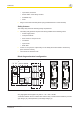
PNOZ s6.1 Preparing for operation } Supply voltage Supply voltage AC } DC Input circuit Input circuit Single-channel Dual-channel Two-hand pushbuttons with detection of shorts across contacts Simultaneity monitoring in safety gate applications with automatic start after the safety gate is closed ATTENTION! *The unit starts automatically when the E-STOP / safety gate device is released.
PNOZ s6.1 } Semiconductor output Legend } S1/S2: Two-hand pushbuttons Operation The unit is ready for operation when the Power LED is permanently lit. LEDs indicate the status and errors during operation: LED on LED flashes Information Status indicators and error indicators may occur independently. In the case of an error display, the "Fault" LED will light or flash (exception: "Supply voltage too low"). An LED that is also flashing indicates the potential cause of the error.
PNOZ s6.1 Fault indicators All LEDs off Diagnostics: Short across contacts/earth fault; unit switched off } Remedy: Rectify short across contacts/earth fault, switch off supply voltage for 1 min. Fault Diagnostics: Plug terminator not connected } Remedy: Insert plug terminator, switch supply voltage off and then on again. Fault Diagnostics: Internal error, unit defective } Remedy: Switch supply voltage off and then on again, change unit if necessary.
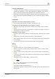
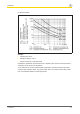
PNOZ s6.1 Faults - malfunctions } Contact malfunctions: If the contacts have welded, reactivation will not be possible after the input circuit has opened. Service life graph The service life graphs indicate the number of cycles from which failures due to wear must be expected. The wear is mainly caused by the electrical load; the mechanical load is negligible.
PNOZ s6.1 UB 48-240 VAC/DC Example } Inductive load: 0,2 A } Utilisation category: AC15 } Contact service life: 1,000,000 cycles Provided the application requires fewer than 1,000,000 cycles, the PFH value (see technical details) can be used in the calculation. To increase the service life, sufficient spark suppression must be provided on all output contacts. With capacitive loads, any power surges that occur must be noted. With contactors, use freewheel diodes for spark suppression.
PNOZ s6.1 Technical details General Approvals 750126 CCC, CE, GOST, KOSHA, TÜV, cULus Listed 750126 Electrical data Supply voltage Voltage 24 V Type DC Voltage tolerance -15 %/+10 % Output of external – power supply (AC) Output of external 3,5 W power supply (DC) Frequency range – AC Residual ripple 20 % DC Continuous duty 100 % Max.
PNOZ s6.1 Semiconductor outputs Number Voltage Current Relay outputs Max. short circuit current IK Utilisation category In accordance with the standard Auxiliary contacts, AC1 at Min. current Max. current Max. power Auxiliary contacts, DC1 at Min. current Max. current Max. power Safety contacts, AC1 at Max. current Min. current Max. power Safety contacts, DC1 at Max. current Min. current Max. power Utilisation category In accordance with the standard Auxiliary contacts, AC15 at Max.
PNOZ s6.
PNOZ s6.
PNOZ s6.
PNOZ s6.1 Safety characteristic data Operating mode EN ISO 13849-1: 2006 PL Emergency PL e stop/safety gate function Two-hand PL c function EN ISO 13849-1: 2006 IEC 61511 IEC 61511 SIL PFD EN ISO 13849-1: 2006 EN IEC 62061 EN IEC 62061 Category Cat. 4 SIL CL PFHD [1/h] SIL CL 3 2,62E-09 SIL 3 3,32E-05 TM [year] 20 Cat. 1 SIL CL 1 5,99E-08 SIL 1 5,10E-03 20 All the units used within a safety function must be considered when calculating the safety characteristic data.
PNOZ s6.1 EC declaration of conformity This product/these products meet the requirements of the directive 2006/42/EC for machinery of the European Parliament and of the Council. The complete EC Declaration of Conformity is available on the Internet at www.pilz.com/downloads. Representative: Norbert Fröhlich, Pilz GmbH & Co. KG, Felix-Wankel-Str. 2, 73760 Ostfildern, Germany Operating Manual PNOZ s6.
In many countries we are represented by our subsidiaries and sales partners. ... Please refer to our homepage for further details or contact our headquarters. Pilz GmbH & Co. KG Felix-Wankel-Straße 2 73760 Ostfildern, Germany Telephone: +49 711 3409-0 Telefax: +49 711 3409-133 E-Mail: pilz.gmbh@pilz.de Internet: www.pilz.com Technical support +49 711 3409-444 support@pilz.