
User guide


PNOZ s5
Operating Manual PNOZ s5
21397-EN-09
9
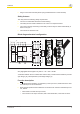
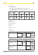
} Semiconductor output
U
B
24 VDC U
B
48 – 240 VAC/DC
*Connect together the 0V connections on all
the external power supplies
Legend
} S1/S2: E-STOP/safety gate switch
} S3: Reset button
}
: Switch operated
}
: Gate open
}
: Gate closed
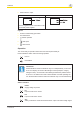
Operation
The unit is ready for operation when the Power LED is permanently lit.
LEDs indicate the status and errors during operation:
LED on
LED flashes
Information
Status indicators and error indicators may occur independently. In the case
of an error display, the "Fault" LED will light or flash (exception: "Supply
voltage too low"). An LED that is also flashing indicates the potential cause
of the error. An LED that is lit and is static indicates a normal operating sta-
tus. Several status indicators and error indicators may occur simultaneously.
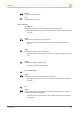
Status indicators
Power
Supply voltage is present.
In1
Input circuit at S12 is closed.
In2
Input circuit at S22 is closed.
Out
Safety contacts are closed and semiconductor output Y32 carries a high signal.