
User guide


PNOZ s5
Operating Manual PNOZ s5
21397-EN-09
6
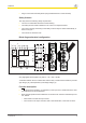
Wiring
Please note:
} Information given in the "Technical details" must be followed.
} Outputs 13-14, 23-24 are instantaneous safety contacts, outputs 37-38, 47-48 are de-
lay-on de-energisation safety contacts.
} Semiconductor output Y32 should not be used for safety circuits!
} To prevent contact welding, a fuse should be connected before the output contacts (see
technical details).
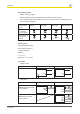
} Calculation of the max. cable length l
max
in the input circuit:
R
lmax
= max. overall cable resistance (see technical details)
R
l
/ km = cable resistance/km
} Use copper wire that can withstand 60/75 °C.
} Sufficient fuse protection must be provided on all output contacts with capacitive and in-
ductive loads.
} With U
B
48 – 240 VAC/DC: Connect S21 to the protective earth system
} When connecting magnetically operated, reed proximity switches, ensure that the max.
peak inrush current (on the input circuit) does not overload the proximity switch.
} On 24 VDC devices:
The power supply must comply with the regulations for extra low voltages with safe
electrical separation (SELV, PELV) in accordance with VDE 0100, Part 410.
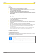
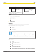
Preparing for operation
Operating modes and delay time
The operating mode and delay time are set via the rotary switches on the unit. You can do
this by opening the cover on the front of the unit.
CAUTION!
Do not adjust the rotary switch during operation, otherwise an error mes-
sage will appear, the safety contacts will open and the unit will not be ready
for operation until the supply voltage has been switched off and then on
again.