
User guide


PNOZ s5
Operating Manual PNOZ s5
21397-EN-09
5
}
Dual-channel operation with detection of shorts across contacts: redundant input cir-
cuit, detects
– earth faults in the start and input circuit,
– short circuits in the input circuit and, with a monitored start, in the start circuit too,
– shorts between contacts in the input circuit.
}
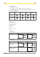
Automatic start: Unit is active once the input circuit has been closed.
} Manual start: Unit is active once the input circuit is closed and then the start circuit is
closed.
}
Monitored start with falling edge: Unit is active once
– the input circuit is closed and then the start circuit is closed and opened again.
– the start circuit is closed and then opened again once the input circuit is closed.
}
Monitored start with rising edge: Unit is active once the input circuit is closed and
once the start circuit is closed after the waiting period has elapsed (see technical de-
tails).
}
Start with start-up test: The unit checks whether safety gates that are closed are
opened and then closed again when supply voltage is applied.
} Ability to increase the number of contacts available on the
– instantaneous safety contacts by using connectors to link to a PNOZsigma contact
expansion module
– delayed/instantaneous safety contacts by connecting contact expansion modules or
external contactors
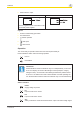
Installation
Install base unit without contact expansion module:
} Ensure that the plug terminator is inserted at the side of the unit.
Connect base unit and PNOZsigma contact expansion module:
} Remove the plug terminator at the side of the base unit and at the contact expansion
module.
} Connect the base unit and the contact expansion module to the supplied connector be-
fore mounting the units to the DIN rail.
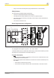
Installation in control cabinet
} The safety relay should be installed in a control cabinet with a protection type of at least
IP54.
} Use the notch on the rear of the unit to attach it to a DIN rail (35 mm).
} When installed vertically: Secure the unit by using a fixing element (e.g. retaining brack-
et or end angle).
} Push the device upwards or downwards before lifting it from the DIN rail.