PNOZ s5 Safety relays Operating Manual-21397-EN-09
Preface This document is the original document. All rights to this documentation are reserved by Pilz GmbH & Co. KG. Copies may be made for internal purposes. Suggestions and comments for improving this documentation will be gratefully received. Pilz®, PIT®, PMI®, PNOZ®, Primo®, PSEN®, PSS®, PVIS®, SafetyBUS p®, SafetyEYE®, SafetyNET p®, the spirit of safety® are registered and protected trademarks of Pilz GmbH & Co. KG in some countries.
PNOZ s5 PNOZ s5 safety relay The safety relay provides a safety-related interruption of a safety circuit. The safety relay meets the requirements of EN 60947-5-1, EN 60204-1 and VDE 0113-1 and may be used in applications with } E-STOP pushbuttons } Safety gates } Light beam devices For your safety } Only install and commission the unit if you have read and understood these operating instructions and are familiar with the applicable regulations for health and safety at work and accident prevention.
PNOZ s5 } Plug-in connection terminals (either spring-loaded terminal or screw terminal) Safety features The relay meets the following safety requirements: } The circuit is redundant with built-in self-monitoring. } The safety function remains effective in the case of a component failure. } The correct opening and closing of the safety function relays is tested automatically in each on-off cycle. } The unit has an electronic fuse.
PNOZ s5 } Dual-channel operation with detection of shorts across contacts: redundant input circuit, detects – earth faults in the start and input circuit, – short circuits in the input circuit and, with a monitored start, in the start circuit too, – shorts between contacts in the input circuit. Automatic start: Unit is active once the input circuit has been closed. } } Manual start: Unit is active once the input circuit is closed and then the start circuit is closed.
PNOZ s5 Wiring Please note: } Information given in the "Technical details" must be followed. } Outputs 13-14, 23-24 are instantaneous safety contacts, outputs 37-38, 47-48 are delay-on de-energisation safety contacts. } Semiconductor output Y32 should not be used for safety circuits! } To prevent contact welding, a fuse should be connected before the output contacts (see technical details). } Calculation of the max. cable length lmax in the input circuit: Rlmax = max.
PNOZ s5 Set operating modes } Switch off supply voltage. } Select operating mode via the operating mode selector switch "mode". } If the operating mode selector switch "mode" is in its start position (vertical position), an error message will appear.
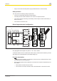
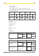
PNOZ s5 Safety gate without detection of shorts across contacts Safety gate with detection of shorts across contacts Light beam device or safety switch with detection of shorts across contacts via ESPE (only when UB = 24 VDC) } Start circuit/feedback loop Start circuit/feedback loop Start circuit Feedback loop Automatic start Monitored, manual sta
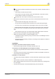
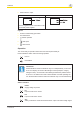
PNOZ s5 } Semiconductor output UB 24 VDC UB 48 – 240 VAC/DC *Connect together the 0V connections on all the external power supplies Legend } S1/S2: E-STOP/safety gate switch } S3: Reset button } : Switch operated } : Gate open } : Gate closed Operation The unit is ready for operation when the Power LED is permanently lit. LEDs indicate the status and errors during operation: LED on LED flashes Information Status indicators and error indicators may occur independently.
PNOZ s5 Reset 24 V DC is present at S34. Out Set delay time is running. Error indicators All LEDs off Diagnostics: Short across contacts/earth fault; unit switched off } Remedy: Rectify short across contacts/earth fault, switch off supply voltage for 1 min. Fault Diagnostics: Plug terminator not connected } Remedy: Insert plug terminator, switch supply voltage off and then on again.
PNOZ s5 In2 Fault Diagnostics: Power-up blocked due to short-term interruption at S22; input circuits not operated simultaneously } Remedy: Open both input circuits, S12 and S22, simultaneously and then close again. Reset Fault Diagnostics: Position of rotary switch is not permitted or rotary switch was adjusted during operation. } Remedy: Switch supply voltage off and then on again.
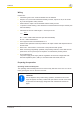
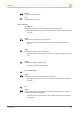
PNOZ s5 Service life graph The service life graphs indicate the number of cycles from which failures due to wear must be expected. The wear is mainly caused by the electrical load; the mechanical load is negligible. Example } Inductive load: 0,2 A } Utilisation category: AC15 } Contact service life: 1,000,000 cycles Provided the application requires fewer than 1,000,000 cycles, the PFH value (see technical details) can be used in the calculation.
PNOZ s5 Technical details General Approvals Electrical data Supply voltage Voltage Type Voltage tolerance Output of external power supply (AC) Output of external power supply (DC) Frequency range AC Residual ripple DC Continuous duty Max. inrush current impulse Reset circuit Feedback loop Max.
PNOZ s5 Electrical data Dual-channel with detection of shorts across contacts at UB AC Min. input resistance at power-on Voltage at Input circuit DC Reset circuit DC Feedback loop DC Current at Input circuit DC Reset circuit DC Feedback loop Number of output contacts Instantaneous safety contacts (N/O) Safety contacts (N/O), delayed Inputs Number Semiconductor outputs Number Voltage Current Relay outputs Max.
PNOZ s5 Relay outputs Safety contacts, delayed: DC1 at Min. current Max. current Max. power Safety contacts, AC1 at Max. current Min. current Max. power Safety contacts, DC1 at Max. current Min. current Max. power Utilisation category In accordance with the standard Safety contacts, delayed: AC15 at Max. current Safety contacts, delayed: DC13 (6 cycles/min) at Max. current Safety contacts, AC15 at Max. current Safety contacts, DC13 (6 cycles/min) at Max.
PNOZ s5 Relay outputs Contact fuse protection, external delayed safety contacts Blow-out fuse, quick Blow-out fuse, slow Circuit breaker, 24 V AC/ DC, characteristic B/C Contact material Conventional thermal current while loading several contacts Ith per contact at UB AC Conv. therm. current with 1 contact Conv. therm. current with 2 contacts Conv. therm. current with 3 contacts Conv. therm. current with 4 contacts Ith per contact at UB DC Conv. therm. current with 1 contact Conv. therm.
PNOZ s5 Times Switch-on delay With automatic reset typ. With automatic reset max. With automatic reset after power on typ. With automatic reset after power on max. With manual reset typ. With manual reset max. With monitored reset with rising edge typ. With monitored reset with rising edge max. With monitored reset with falling edge typ. With monitored reset with falling edge max. Delay-on de-energisation With E-STOP typ. With E-STOP max. With power failure typ. With power failure max.
PNOZ s5 Times Delay time tv 750105 0,00 s, 0,10 s, 0,20 s, 0,30 s, 0,40 s, 0,50 s, 0,60 s, 0,70 s, 0,80 s, 1,00 s, 1,50 s, 10,00 s, 100,00 s, 12,00 s, 120,00 s, 14,00 s, 140,00 s, 15,00 s, 150,00 s, 16,00 s, 160,00 s, 180,00 s, 2,00 s, 2,50 s, 20,00 s, 200,00 s, 210,00 s, 240,00 s, 25,00 s, 3,00 s, 3,50 s, 30,00 s, 300,00 s, 35,00 s, 4,00 s, 40,00 s, 5,00 s, 50,00 s, 6,00 s, 60,00 s, 7,00 s, 70,00 s, 8,00 s, 80,00 s, 90,00 s Repetition accu- +/-1 % + +/-20 racy ms Repetition accu- +/-15 % + +/-20 racy in
PNOZ s5 Environmental data Climatic suitability Ambient temperature Temperature range Storage temperature Temperature range EMC 750105 750135 751105 751135 751185 EN 60068-2-78 EN 60068-2-78 EN 60068-2-78 EN 60068-2-78 EN 60068-2-78 -10 - 55 °C -10 - 55 °C -10 - 55 °C -10 - 55 °C -10 - 55 °C -40 - 85 °C -40 - 85 °C -40 - 85 °C -40 - 85 °C -40 - 85 °C EN 60947-5-1, EN 61000-6-2, EN 61000-6-4 EN 60947-5-1, EN 61000-6-2, EN 61000-6-4 EN 60947-5-1, EN 61000-6-2, EN 61000-6-4 EN 60947-5-
PNOZ s5 Mechanical data 750105 Cross section of external conductors with screw terminals 1 core flexible 0,25 - 2,50 mm², 24 - 12 AWG 2 core with 0,25 - 1,00 mm², the same 24 - 16 AWG cross section, flexible with crimp connectors, no plastic sleeve 2 core with 0,20 - 1,50 mm², the same 24 - 16 AWG cross section, flexible without crimp connectors or with TWIN crimp connectors 0,50 Nm Torque setting with screw terminals Connection type Screw terminal Mounting type Cross section of external conductors with sp
PNOZ s5 Safety characteristic data Operating mode EN ISO 13849-1: 2006 PL Safety con- PL e tacts, instantaneous Safety con- PL e tacts, delayed EN ISO 13849-1: 2006 IEC 61511 IEC 61511 SIL PFD EN ISO 13849-1: 2006 EN IEC 62061 EN IEC 62061 Category Cat. 4 SIL CL PFHD [1/h] SIL CL 3 2,31E-09 SIL 3 2,03E-06 TM [year] 20 Cat. 4 SIL CL 3 2,34E-09 SIL 3 2,75E-05 20 All the units used within a safety function must be considered when calculating the safety characteristic data.
PNOZ s5 EC declaration of conformity This product/these products meet the requirements of the directive 2006/42/EC for machinery of the European Parliament and of the Council. The complete EC Declaration of Conformity is available on the Internet at www.pilz.com/downloads. Representative: Norbert Fröhlich, Pilz GmbH & Co. KG, Felix-Wankel-Str.
In many countries we are represented by our subsidiaries and sales partners. ... Please refer to our homepage for further details or contact our headquarters. Pilz GmbH & Co. KG Felix-Wankel-Straße 2 73760 Ostfildern, Germany Telephone: +49 711 3409-0 Telefax: +49 711 3409-133 E-Mail: pilz.gmbh@pilz.de Internet: www.pilz.com Technical support +49 711 3409-444 support@pilz.