PNOZ s4 Safety relays Operating Manual21396EN13
Preface This document is a translation of the original document. All rights to this documentation are reserved by Pilz GmbH & Co. KG. Copies may be made for internal purposes. Suggestions and comments for improving this documentation will be gratefully received. Pilz®, PIT®, PMI®, PNOZ®, Primo®, PSEN®, PSS®, PVIS®, SafetyBUS p®, SafetyEYE®, SafetyNET p®, the spirit of safety® are registered and protected trademarks of Pilz GmbH & Co. KG in some countries.
Content Introduction Validity of documentation Retaining the documentation Definition of symbols 4 4 4 4 PNOZ s4 safety relay 5 For your safety 5 Unit features 5 Safety features 6 Block diagram/terminal configuration 6 Function description 7 Installation 7 Wiring 8 Preparing for operation Operating modes Set operating modes Connection 8 8 8 9 Operation Status indicators Error indicators 11 11 11 Faults malfunctions 13 Service life graph 13 Technical details Safety characteristic
PNOZ s4 Introduction Validity of documentation This documentation is valid for the product PNOZ s4. It is valid until new documentation is published. This operating manual explains the function and operation, describes the installation and provides guidelines on how to connect the product. Retaining the documentation This documentation is intended for instruction and should be retained for future reference.
PNOZ s4 INFORMATION This gives advice on applications and provides information on special fea tures. PNOZ s4 safety relay The safety relay provides a safetyrelated interruption of a safety circuit.
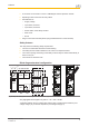
PNOZ s4 } A connector can be used to connect 1 PNOZsigma contact expansion module } Operating modes can be set via rotary switch } LED indicator for: } – Supply voltage – Input status, channel 1 – Input status, channel 2 – Switch status of the safety contacts – Start circuit – Errors Plugin connection terminals (either springloaded terminal or screw terminal) Safety features The relay meets the following safety requirements: } The circuit is redundant with builtin selfmonitoring.
PNOZ s4 Function description } Singlechannel operation: no redundancy in the input circuit, earth faults in the start circuit and input circuit are detected. } Dualchannel operation without detection of shorts across contacts: redundant input cir cuit, detects } In2+ – earth faults in the start and input circuit, – short circuits in the input circuit and, with a monitored start, in the start circuit too.
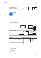
PNOZ s4 } Push the device upwards or downwards before lifting it from the DIN rail. Wiring Please note: } Information given in the "Technical details" must be followed. } Outputs 1314, 2324, 3334 are safety contacts; output 4142 is an auxiliary contact (e.g. for display). } Auxiliary contact 4142 and semiconductor output Y32 should not be used for safety circuits! } To prevent contact welding, a fuse should be connected before the output contacts (see technical details).
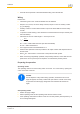
PNOZ s4 Operating mode Automatic/ selector switch manual start "mode" Without detec tion of shorts across contacts In2+ In2- With detection of shorts across contacts In2+ In2- Monitored start rising edge Monitored start falling edge Automatic start with startup test In2+ In2- In2+ In2- In2+ In2- In2+ In2- In2+ In2- In2+ In2- Connection } Supply voltage Supply voltage AC S21 } DC A1 L A1 L+ A2 N A2 L- Input circuit Input circuit ESTOP without detection of shorts across contact
PNOZ s4 24 V DC Light beam device or safety switch with detection of shorts across contacts via ESPE (only when UB = 24 VDC) A2 S12 S22 GND NOTICE When used as a safety component in accordance with EN 811: – The switch that is used must be designed as a safety switch in ac cordance with 14.1.2.2 of EN 811, so that a failure to open when en ergised is excluded. – The supply lines to the safety switch must be laid in accordance with 13.
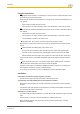
PNOZ s4 Operation The unit is ready for operation when the Power LED is permanently lit. LEDs indicate the status and errors during operation: LED on LED flashes INFORMATION Status indicators and error indicators may occur independently. In the case of an error display, the "Fault" LED will light or flash (exception: "Supply voltage too low"). An LED that is also flashing indicates the potential cause of the error. An LED that is lit and is static indicates a normal operating status.
PNOZ s4 Fault Diagnostics: Internal error, unit defective } Remedy: Switch supply voltage off and then on again, change unit if neces sary. Power Diagnostics: Supply voltage too low } Remedy: Check the supply voltage. In1, In2 alternately Fault Diagnostics: Short detected between S12 and S22 } Remedy: Rectify short across contacts, switch supply voltage off and then on again.
PNOZ s4 Power, In1, In2, Out, Reset, Fault Diagnostics: The operating mode selector switch "mode" is in its start position (vertical position) } Remedy: Switch off the supply voltage and set the required operating mode on operating mode selector switch "mode". Faults malfunctions } Contact malfunctions: If the contacts have welded, reactivation will not be possible after the input circuit has opened.
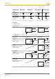
PNOZ s4 UB 48240 VAC/DC Example } Inductive load: 0,2 A } Utilisation category: AC15 } Contact service life: 1,000,000 cycles Provided the application requires fewer than 1,000,000 cycles, the PFH value (see tech nical details) can be used in the calculation. To increase the service life, sufficient spark suppression must be provided on all output contacts. With capacitive loads, any power surges that occur must be noted. With contact ors, use freewheel diodes for spark suppression.
PNOZ s4 Electrical data Supply voltage Voltage Kind Voltage tolerance Output of external power supply (AC) Output of external power supply (DC) Frequency range AC Residual ripple DC Continuous duty Max. inrush current im pulse Current pulse, A1 Pulse duration, A1 Current pulse, input cir cuit Pulse duration, input circuit Current pulse, feed back loop Pulse duration, feed back loop Current pulse, start cir cuit Pulse duration, start circuit Max.
PNOZ s4 Electrical data Voltage at Input circuit DC Start circuit DC Feedback loop DC Current at Input circuit DC Start circuit DC Feedback loop Number of output con tacts Safety contacts (N/O), instantaneous Auxiliary contacts (N/C) Inputs Number Semiconductor outputs Number Voltage Current Relay outputs Max. short circuit current IK Utilisation category In accordance with the standard Auxiliary contacts, AC1 at Min. current Max. current Max. power Auxiliary contacts, DC1 at Min. current Max.
PNOZ s4 Relay outputs Utilisation category In accordance with the standard Auxiliary contacts AC15 at Max. current Auxiliary contacts, DC13 (6 cycles/min) at Max. current Safety contacts, AC15 at Max. current Safety contacts DC13 (6 cycles/min) at Max.
PNOZ s4 Times Switchon delay With automatic start typ. With automatic start max. With automatic start after power on typ. With automatic start after power on max. With manual start typ. With monitored start with rising edge typ. With monitored start with rising edge max. With monitored start with falling edge typ. With monitored start with falling edge max. Delayon deenergisation With ESTOP typ. With ESTOP max. With power failure typ. With power failure max. With power failure typ.
PNOZ s4 Environmental data Storage temperature Temperature range EMC Vibration In accordance with the standard Frequency Amplitude Airgap creepage In accordance with the standard Overvoltage category Pollution degree Rated insulation voltage Rated impulse withstand voltage Protection type Mounting area (e.g.
PNOZ s4 Mechanical data Conductor cross section with springloaded termin als: Flexible with/without crimp connector Springloaded terminals: Terminal points per con nection Stripping length Dimensions Height Width Depth Weight 750104 750134 751104 – – 0,20 2,50 mm², 24 12 AWG – – – – 2 9 mm 98,0 mm 22,5 mm 120,0 mm 190 g 98,0 mm 22,5 mm 120,0 mm 215 g 100,0 mm 22,5 mm 120,0 mm 190 g Order no.
PNOZ s4 Electrical data Max. overall cable resistance Rl max Singlechannel at UB DC Singlechannel at UB AC Dualchannel without detection of shorts across contacts at UB DC Dualchannel without detection of shorts across contacts at UB AC Dualchannel with detection of shorts across contacts at UB DC Dualchannel with detection of shorts across contacts at UB AC Min.
PNOZ s4 Relay outputs Utilisation category In accordance with the standard Auxiliary contacts, AC1 at Min. current Max. current Max. power Auxiliary contacts, DC1 at Min. current Max. current Max. power Safety contacts, AC1 at Max. current Min. current Max. power Safety contacts, DC 1 at Max. current Min. current Max. power Utilisation category In accordance with the standard Auxiliary contacts AC15 at Max. current Auxiliary contacts, DC13 (6 cycles/min) at Max. current Safety contacts, AC15 at Max.
PNOZ s4 Conventional thermal current while loading several contacts Ith per contact at UB AC Conv. therm. current with 1 con tact Conv. therm. current with 2 con tacts Conv. therm. current with 3 con tacts Ith per contact at UB DC Conv. therm. current with 1 con tact Conv. therm. current with 2 con tacts Conv. therm. current with 3 con tacts Times Switchon delay With automatic start typ. With automatic start max. With automatic start after power on typ. With automatic start after power on max.
PNOZ s4 Times Min.
PNOZ s4 Mechanical data Dimensions Height Width Depth Weight 751134 751184 100,0 mm 22,5 mm 120,0 mm 215 g 100,0 mm 22,5 mm 120,0 mm 190 g The standards current on 200912 apply. Safety characteristic data Operating mode EN ISO 138491: 2008 EN ISO 138491: 2008 PL Category Safety con tacts, in stantaneous PL e Cat.
PNOZ s4 Order reference Product type Features PNOZ s4 PNOZ s4 24 V DC 48 – 240 V AC/DC PNOZ s4 C PNOZ s4 C 24 V DC 48 – 240 V AC/DC PNOZ s4 C Coated Terminals Order no. Screw terminals 750 104 Screw terminals 750 134 Springloaded terminals 751 104 Springloaded terminals 751 134 24 V DC Springloaded terminals 751 184 EC declaration of conformity This product/these products meet the requirements of the directive 2006/42/EC for ma chinery of the European Parliament and of the Council.
In many countries we are represented by our subsidiaries and sales partners. ... Please refer to our homepage for further details or contact our headquarters. Pilz GmbH & Co. KG Felix-Wankel-Straße 2 73760 Ostfildern, Germany Telephone: +49 711 3409-0 Telefax: +49 711 3409-133 E-Mail: pilz.gmbh@pilz.de Internet: www.pilz.com Technical support +49 711 3409-444 support@pilz.