PNOZ s3 Safety relays Operating Manual-21395-EN-10
Preface This document is the original document. All rights to this documentation are reserved by Pilz GmbH & Co. KG. Copies may be made for internal purposes. Suggestions and comments for improving this documentation will be gratefully received. Pilz®, PIT®, PMI®, PNOZ®, Primo®, PSEN®, PSS®, PVIS®, SafetyBUS p®, SafetyEYE®, SafetyNET p®, the spirit of safety® are registered and protected trademarks of Pilz GmbH & Co. KG in some countries.
PNOZ s3 PNOZ s3 safety relay The safety relay provides a safety-related interruption of a safety circuit. The safety relay meets the requirements of EN 60947-5-1, EN 60204-1 and VDE 0113-1 and may be used in applications with } E-STOP pushbuttons } Safety gates } Light beam devices For your safety } Only install and commission the unit if you have read and understood these operating instructions and are familiar with the applicable regulations for health and safety at work and accident prevention.
PNOZ s3 Safety features The relay meets the following safety requirements: } The circuit is redundant with built-in self-monitoring. } The safety function remains effective in the case of a component failure. } The correct opening and closing of the safety function relays is tested automatically in each on-off cycle. } The unit has an electronic fuse.
PNOZ s3 } Manual start: Unit is active once the input circuit is closed and then the start circuit is closed. Monitored start with falling edge: Unit is active once } – the input circuit is closed and then the start circuit is closed and opened again. – the start circuit is closed and then opened again once the input circuit is closed.
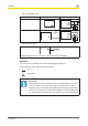
PNOZ s3 } Calculation of the max. cable length lmax in the input circuit: Rlmax = max. overall cable resistance (see technical details) Rl / km = cable resistance/km } Use copper wire that can withstand 60/75 °C. } Sufficient fuse protection must be provided on all output contacts with capacitive and inductive loads. } When connecting magnetically operated, reed proximity switches, ensure that the max.
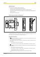
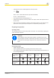
PNOZ s3 Connection } Supply voltage Supply voltage } AC DC Input circuit Input circuit Emergency stop without detection of shorts across contacts Single-channel Dual-channel Emergency stop with detection of shorts across contacts Safety gate without detection of shorts across contacts Safety gate with detection of shorts across contacts Light beam device or safety sw
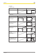
PNOZ s3 } Start circuit/feedback loop Start circuit/feedback loop Start circuit Feedback loop Automatic start Manual/monitored start } Semiconductor output *Connect together the 0V connections on all the external power supplies Operation The unit is ready for operation when the Power LED is permanently lit.
PNOZ s3 Status indicators Power Supply voltage is present. In1 Input circuit at S12 is closed. In2 Input circuit at S22 is closed. Out Safety contacts are closed and semiconductor output Y32 carries a high signal. Reset 24 V DC is present at S34. Error indicators All LEDs off Diagnostics: Short across contacts/earth fault; unit switched off } Remedy: Rectify short across contacts/earth fault, switch off supply voltage for 1 min.
PNOZ s3 In1 Fault Diagnostics: Power-up blocked due to short-term interruption at S12; input circuits not operated simultaneously } Remedy: Open both input circuits, S12 and S22, simultaneously and then close again. In2 Fault Diagnostics: Power-up blocked due to short-term interruption at S22; input circuits not operated simultaneously } Remedy: Open both input circuits, S12 and S22, simultaneously and then close again.
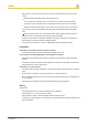
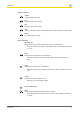
PNOZ s3 Service life graph The service life graphs indicate the number of cycles from which failures due to wear must be expected. The wear is mainly caused by the electrical load; the mechanical load is negligible. Example } Inductive load: 0,2 A } Utilisation category: AC15 } Contact service life: 2,000,000 cycles Provided the application requires fewer than 2,000,000 cycles, the PFH value (see technical details) can be used in the calculation.
PNOZ s3 Technical Details General Approvals Electrical data Supply voltage Voltage Type Voltage tolerance Output of external power supply (DC) Residual ripple DC Continuous duty Max. inrush current impulse A1 Pulse duration Reset circuit Feedback loop Max. overall cable resistance Rlmax Single-channel at UB DC Dual-channel without detection of shorts across contacts at UB DC Dual-channel with detection of shorts across contacts at UB DC Min.
PNOZ s3 Relay outputs Max. short circuit current IK Utilisation category In accordance with the standard Safety contacts, AC1 at Max. current Min. current Max. power Safety contacts, DC1 at Max. current Min. current Max. power Utilisation category In accordance with the standard Safety contacts, AC15 at Max. current Safety contacts, DC13 (6 cycles/ min) at Max.
PNOZ s3 Times Delay-on de-energisation With E-STOP typ. With E-STOP max. With power failure typ. With power failure max. Recovery time at max. switching frequency 1/s After E-STOP After power failure Waiting period with a monitored reset With rising edge With falling edge Min.
PNOZ s3 Mechanical data Mounting position Mechanical life Material Bottom Front Top Cross section of external conductors with screw terminals 1 core flexible 2 core with the same cross section, flexible with crimp connectors, no plastic sleeve 2 core with the same cross section, flexible without crimp connectors or with TWIN crimp connectors Torque setting with screw terminals Connection type Mounting type Cross section of external conductors with spring-loaded terminals: flexible with/without crimp connec
PNOZ s3 Information A safety function's SIL/PL values are not identical to the SIL/PL values of the units that are used and may be different. We recommend that you use the PAScal software tool to calculate the safety function's SIL/PL values. ATTENTION! It is essential to consider the relay's service life graphs. The relay outputs' safety-related characteristic data is only valid if the values in the service life graphs are met.
In many countries we are represented by our subsidiaries and sales partners. ... Please refer to our homepage for further details or contact our headquarters. Pilz GmbH & Co. KG Felix-Wankel-Straße 2 73760 Ostfildern, Germany Telephone: +49 711 3409-0 Telefax: +49 711 3409-133 E-Mail: pilz.gmbh@pilz.de Internet: www.pilz.com Technical support +49 711 3409-444 support@pilz.