
Owner's manual

- 4 -
Inbetriebnahme
Beachten Sie bei der Inbetriebnahme:
• Nur die Ausgangskontakte 13-14/23-24/
33-34 sind Sicherheitskontakte.
Ausgangskontakt 41-42 und die
Halbleiterausgänge Y32 und Y35 sind
Hilfsausgänge (z. B. für Anzeige oder
die ungefährliche Aufwärtsbewegung).
• Hilfskontakt 41-42 und Halbleiteraus-
gänge Y32 und Y35 nicht für
Sicherheitsstromkreise verwenden!
• Vor die Ausgangskontakte eine
Sicherung (4 A träge/6 A flink) schal-
ten, um das Verschweißen der Kontak-
te zu verhindern.
• Leitungsmaterial aus Kupferdraht mit
einer Temperaturbeständigkeit von
60/75 °C verwenden.
• Keine kleinen Ströme mit Kontakten
schalten, über die zuvor große Ströme
geführt wurden.
• Das Netzteil muss den Vorschriften für
Funktionskleinspannungen mit sicherer
elektrischer Trennung (SELV, PELV) nach
VDE 0100, Teil 410 entsprechen.
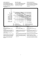
• Berechnung der max. Leitungslänge I
max
im Eingangskreis:
R
lmax
R
l
/ km
I
max
=
R
lmax
= max. Gesamtleitungs
widerstand (s. technische Daten)
R
l
/km = Leitungswiderstand/km
• Angaben im Kapitel „Technische Daten“
unbedingt einhalten.
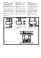
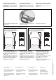
Ablauf:
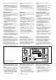
• Versorgungsspannung an Klemmen A1
(L+) und A2 (L-) anlegen.
Die Versorgungsspannung muss mit der
Antriebsenergie der Maschine (Presse)
abgeschaltet werden.
• Rückführkreis:
Brücke an Y1-Y2 oder externe Schütze
anschließen.
• Eingangskreis
- Taster 1: Öffnerkontakt zwischen S11-
S12 und Schließerkontakt zwischen
S11-S13 anschließen
- Taster 2: Öffnerkontakt zwischen S21-
S22 und Schließerkontakt zwischen
S21-S23 anschließen
• Halbleiterausgänge:
+24 V DC an Klemme Y31 und 0 V an
Klemme Y30 anschließen. Y32 und Y35
mit 24-V-Eingängen einer SPS verbinden.
Die Sicherheitskontakte 13-14/23-24/33-34
sind geöffnet, der Hilfskontakt 41-42 ist
geschlossen.
Fehler - Störungen
Das Gerät kann aus Sicherheitsgründen bei
folgenden Fehlern nicht gestartet werden:
• Verschweißte Kontakte
• Defekte Spule
• Leiterbruch
• Kurzschluss z. B. zwischen den Tastern
• Nicht Einhalten der Gleichzeitigkeit
Operation
Please note for operation:
• Only the output contacts 13-14/23-24/
33-34 are safety contacts. Output
contact 41-42 and semiconductor
outputs Y32 and Y35 are auxiliary
outputs (e.g. for a display or the safe
upwards movement).
• Do not use auxiliary contact 41-42 and
semiconductor outputs Y32 and Y35
for safety circuits!
• To prevent a welding together of the
contacts, a fuse (4 A slow/ 6 A quick
acting) must be connected before the
output contacts.
• Use copper wire that can withstand
60/75 °C.
• Low currents should not be switched
across contacts across which high
currents have previously been switched.
• The power supply must comply with the
regulations for extra low voltages with safe
electrical separation (SELV, PELV) in
accordance with VDE 0100, Part 410.
• Calculate the max. Cable runs I
max
in the
input circuit:
R
lmax
R
l
/ km
I
max
=
R
lmax
= Max. Total cable resistance (see
technical details)
R
l
/km = Cable resistance/km
• Important details in the section "Technical
Data" should be noted and adhered to.
To operate:
• Supply operating voltage to terminals A1
(L+) and A2 (L-).
The operating voltage must be turned off
with the driving power of the press.
• Feedback control loop
Bridge Y1 - Y2 or connect external
contactors/relays.
• Input circuit:
- Button 1: Connect N/C contact between
S11-S12 and N/O contact between
S11-S13
- Button 2: Connect N/C contact between
S21-S22 and N/O contact between
S21-S23
• Connect +24 VDC on terminals Y31 and
0 V on terminals Y30. Connect Y32 and
Y35 with 24 V input of a PLC.
The safety contacts 13-14/23-24/33-34 are
opened and the auxilliary contact 41-42 is
closed.
Faults
For safety reasons, the unit will not energise
when the following faults occur:
• Welded contacts
• Defective coil
• Cable-break
• Short-circuit e.g. between the buttons
• Simultaneity not upheld
Mise en oeuvre
Informations préliminaires :
• Seuls les contacts 13-14/23-24/33-34
sont des contacts de sécurité. Le
contact 41-42 et les sorties statiques
sont des sorties d'information (ex. :
affichage, pilotage du mouvement de
montée).
• Ne pas utiliser le contact d’information
41-42 et les sorties statiques Y32 et
Y35 pour les circuits de commande de
sécurité !
• Installez des fusibles 4 A normaux/6 A
rapides en amont des contacts de
sortie pour éviter leur soudage.
• Utiliser uniquement des fils de câblage en
cuivre 60/75 °C.
• Ne pas commuter de faibles intensités par
des contacts ayant au préalable
commutés des intensités plus élevées.
• L'alimentation doit satisfaire aux
prescriptions relatives aux tensions extra
basses avec une isolation électrique de
sécurité (SELV, PELV) selon VDE 0100,
partie 410.
• Calcular les longueurs de câblage max
I
max
dans le circuit d’entrée:
R
lmax
R
l
/ km
I
max
=
R
lmax
= résistivité de câblage totale max.
(voir les caractéristiques techniques)
R
l
/km = résistivité de câblage/km
• Respectez les données indiquées dans
les caractéristiques techniques
Mise en oeuvre :
• Ramenez la tension d'alimentation sur les
bornes A1 (L+) et A2 (L-).
La tension d'alimentation du boîtier doit
être coupée avec la tension de puissance
de la presse.
• Boucle de retour :
Pont sur Y1-Y2 ou branchement des
contacts des contacteurs externes
• Canaux d'entrée :
- Poussoir 1: relier le contact à ouverture
entre S11-S12 et le contact à fermeture
entre S11-S13
- Poussoir 2: relier le contact à ouverture
entre S21-S22 et le contact à fermeture
entre S21-S23
• Sorties statiques
Relier le +24 VDC à la borne Y31 et le 0
V à la borne Y30. Relier les sorties Y32 et
Y35 à des entrées 24 V API.
Les contacts de sécurité 13-14/23-24/33-34
sont ouverts, le contact d'info. 41-42 est
fermé.
Erreurs - Défaillances
Compte tenu de sa fonction de sécurité,
l'appareil ne peut être activé après les
défaillances suivantes :
• Collage d'un contact
• Défaillance d'une bobine
• Rupture d'une piste de circuit imprimé
• Court-circuit entre les poussoirs
• non respect du temps de
désynchronisme.