
User Manual


PNOZ 11
Operating Manual PNOZ 11
19147-EN-05
7
Unit features
} Positive-guided relay outputs:
– 7 safety contacts (N/O), instantaneous
– 1 auxiliary contact (N/C), instantaneous
} 2 semiconductor outputs
} Connection options for:
– E-STOP pushbutton
– Safety gate limit switch
– Start button
} LED indicator for:
– Supply voltage
– Input state
– Switch state of the safety contacts
– Start circuit
} Semiconductor outputs signal:
– Supply voltage is present
– Switch status of the safety contacts
} See order reference for unit types
Safety features
The safety relay meets the following safety requirements:
} The circuit is redundant with built-in self-monitoring.
} The safety function remains effective in the case of a component failure.
} The correct opening and closing of the safety function relays is tested automatically in
each on-off cycle.
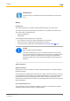
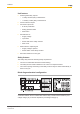
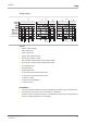
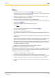
Block diagram/terminal configuration
A1 A2
B1 B2
*Insulation between the non-marked area and the relay contacts: Basic insulation (over-
voltage category III), Protective separation (overvoltage category II)